DTC P30DF-62: Backup Boost Converter Circuit Board (Thermistor) Signal Compare Failure; DTC P30EF-4B: Backup Boost Converter Circuit Board Over Temperature; DTC P323A-00: Backup Boost Converter "A"; DTC P323A-16: Backup Boost Converter "A" Circuit Voltage Below Threshold; DTC P323A-A2: Backup Boost Converter "A" System Voltage Low; DTC P323B-29: Backup Boost Converter "A" Control Circuit Signal Invalid; DTC P323B-38: Backup Boost Converter "A" Control Circuit Signal Cycle Invalid [12/2019 - 10/2022]: Procedure
- CHECK HARNESS AND CONNECTOR (BIN1 AND BIN2 TERMINALS POWER SOURCE CIRCUIT)
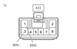
*a Front view of wire harness connector
(to Engine Stop and Start ECU)- Disconnect the engine stop and start ECU connector.
- Measure the voltage according to the value(s) in the table below.
Standard Voltage
Tester Connection Condition Specified Condition A33-1 (BIN2) - Body ground Always 9.5 to 14 V A33-3 (BIN1) - Body ground Always 9.5 to 14 V Result
Proceed to OK NG
Result:
NG
REPAIR OR REPLACE HARNESS OR CONNECTOR (ENGINE STOP AND START ECU - BATTERY)
Result:
OK
See step 2
- CHECK HARNESS AND CONNECTOR (IG1 TERMINAL POWER SOURCE CIRCUIT)
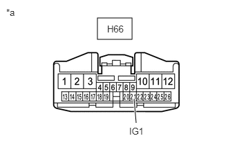
*a Front view of wire harness connector
(to Engine Stop and Start ECU)- Disconnect the engine stop and start ECU connector.
- Turn the ignition switch to ON.
- Measure the voltage according to the value(s) in the table below.
Standard Voltage
Tester Connection Condition Specified Condition H66-21 (IG1) - Body ground Ignition switch ON 9.5 to 14 V Result
Proceed to OK NG
Result:
NG
REPAIR OR REPLACE HARNESS OR CONNECTOR (ENGINE STOP AND START ECU - INSTRUMENT PANEL JUNCTION BLOCK ASSEMBLY (IG1-NO. 1 RELAY))
Result:
OK
See step 3
- CHECK HARNESS AND CONNECTOR (ENGINE STOP AND START ECU - BODY GROUND)
- Disconnect the engine stop and start ECU connector.
- Measure the resistance according to the value(s) in the table below.
Standard Resistance
Tester Connection Condition Specified Condition A34-6 (DGND) - Body ground Always Below 1 Ω Result
Proceed to OK NG
Result:
NG
REPAIR OR REPLACE HARNESS OR CONNECTOR
Result:
OK
See step 4
- CHECK HARNESS AND CONNECTOR (ENGINE STOP AND START ECU - EACH ECU OR SENSOR)
- Disconnect the engine stop and start ECU connector.
- Remove the FOG FR relay from the No. 1 engine room relay block and No. 1 junction block assembly. (w/ Front Fog Light)
- Disconnect the integration control sub-assembly connector. (w/ 12.3 Inch Display)
- Disconnect the tire pressure warning ECU and receiver connector.
- Disconnect the navigation ECU connector. (w/ Navigation System)
- Disconnect the meter mirror assembly connector. (w/ Headup Display)
- Disconnect the radio and display receiver assembly connector. (w/o 12.3 Inch Display)
- Disconnect the radio receiver assembly connector. (w/ 12.3 Inch Display)
- Disconnect the multi-display assembly connector. (w/ 12.3 Inch Display)
- Disconnect the television display assembly connector. (w/ Rear Seat Entertainment System)
- Disconnect the inner rear view mirror assembly connector. (w/ EC Mirror or Digital Inner Mirror)
- Disconnect the front door ambient light LH (front door trim board sub-assembly LH) connector. (w/ Ambient Illumination Light)
- Disconnect the front door ambient light RH (front door trim board sub-assembly RH) connector. (w/ Ambient Illumination Light)
- Disconnect the rear door ambient light LH (rear door trim board sub-assembly LH) connector. (w/ Ambient Illumination Light)
- Disconnect the rear door ambient light RH (rear door trim board sub-assembly RH) connector. (w/ Ambient Illumination Light)
- Disconnect the front passenger side tray illumination light (No. 1 instrument panel light sub-assembly) connector. (w/ Ambient Illumination Light)
- Disconnect the center tray illumination light (No. 1 instrument panel light sub-assembly) connector. (w/ Ambient Illumination Light)
- Disconnect the air conditioning control assembly connector.
- Disconnect the central gateway ECU (network gateway ECU) connector.
- Disconnect the millimeter wave radar sensor assembly connector.
- Disconnect the clearance warning ECU assembly connector.
- Disconnect the blind spot monitor sensor LH connector.
- Disconnect the blind spot monitor sensor RH connector.
- Disconnect the No. 2 air conditioning control assembly connector.
- Measure the resistance according to the value(s) in the table below.
Standard Resistance
Tester Connection Condition Specified Condition H66-2 (B41) - 2 (FOG FR relay)*1 Always Below 1 Ω H66-2 (B41) - 5 (FOG FR relay)*1 Always Below 1 Ω H66-2 (B41) - H8-1 (B)*3 Always Below 1 Ω H66-2 (B41) - M51-7 (+B) Always Below 1 Ω H66-2 (B41) - H18-10 (+B)*2 Always Below 1 Ω H66-2 (B41) - H31-2 (B)*5 Always Below 1 Ω H66-12 (B42) - H1-4 (+B1)*4 Always Below 1 Ω H66-12 (B42) - H4-4 (+B1)*3 Always Below 1 Ω H66-11 (B43) - H7-12 (B)*3 Always Below 1 Ω H66-11 (B43) - R16-1 (+B)*6 Always Below 1 Ω H66-11 (B43) - R1-6 (B)*7 Always Below 1 Ω H66-11 (B43) - R1-6 (+B)*8 Always Below 1 Ω H66-11 (B43) -J26-2 (+)*10 Always Below 1 Ω H66-11 (B43) -J10-2 (+)*10 Always Below 1 Ω H66-11 (B43) -K10-2 (+)*10 Always Below 1 Ω H66-11 (B43) -K5-2 (+)*10 Always Below 1 Ω H66-11 (B43) -H69-2 (ILL+)*10 Always Below 1 Ω H66-11 (B43) -H68-2 (ILL+)*10 Always Below 1 Ω H66-3 (IG41) - H8-4 (IG+)*3 Always Below 1 Ω H66-3 (IG41) - R1-1 (IG)*9 Always Below 1 Ω H66-3 (IG41) - M51-1 (IG) Always Below 1 Ω H66-3 (IG41) - H31-1 (IG+)*5 Always Below 1 Ω H66-3 (IG41) - H27-4 (IG+)*3 Always Below 1 Ω H66-3 (IG41) - H27-6 (IG+)*4 Always Below 1 Ω H66-3 (IG41) - H59-11 (IG1) Always Below 1 Ω H66-3 (IG41) - B6-8 (IGB) Always Below 1 Ω H66-3 (IG41) - H46-1 (IG) Always Below 1 Ω H66-3 (IG41) - M43-5 (BLB) Always Below 1 Ω H66-3 (IG41) - M2-5 (BRB) Always Below 1 Ω H66-3 (IG41) - T2-9 (IG) Always Below 1 Ω H66-2 (B41) or 2 (FOG FR relay)*1 - Body ground and other terminals Always 10 kΩ or higher H66-2 (B41) or 5 (FOG FR relay)*1 - Body ground and other terminals Always 10 kΩ or higher H66-2 (B41) or H8-1 (B)*3 - Body ground and other terminals Always 10 kΩ or higher H66-2 (B41) or M51-7 (+B) - Body ground and other terminals Always 10 kΩ or higher H66-2 (B41) or H18-10 (+B)*2 - Body ground and other terminals Always 10 kΩ or higher H66-2 (B41) or H31-2 (B)*5 - Body ground and other terminals Always 10 kΩ or higher H66-12 (B42) or H1-4 (+B1)*4 - Body ground and other terminals Always 10 kΩ or higher H66-12 (B42) or H4-4 (+B1)*3 - Body ground and other terminals Always 10 kΩ or higher H66-11 (B43) or H7-12 (B)*3 - Body ground and other terminals Always 10 kΩ or higher H66-11 (B43) or R16-1 (+B)*6 - Body ground and other terminals Always 10 kΩ or higher H66-11 (B43) or R1-6 (B)*7 - Body ground and other terminals Always 10 kΩ or higher H66-11 (B43) or R1-6 (+B)*8 - Body ground and other terminals Always 10 kΩ or higher H66-11 (B43) or J26-2 (+)*10 - Body ground and other terminals Always 10 kΩ or higher H66-11 (B43) or J10-2 (+)*10 - Body ground and other terminals Always 10 kΩ or higher H66-11 (B43) or K10-2 (+)*10 - Body ground and other terminals Always 10 kΩ or higher H66-11 (B43) or K5-2 (+)*10 - Body ground and other terminals Always 10 kΩ or higher H66-11 (B43) or H69-2 (ILL+)*10 - Body ground and other terminals Always 10 kΩ or higher H66-11 (B43) or H68-2 (ILL+)*10 - Body ground and other terminals Always 10 kΩ or higher H66-3 (IG41) or H8-4 (IG+)*3 - Body ground and other terminals Always 10 kΩ or higher H66-3 (IG41) or R1-1 (IG)*9 - Body ground and other terminals Always 10 kΩ or higher H66-3 (IG41) or M51-1 (IG) - Body ground and other terminals Always 10 kΩ or higher H66-3 (IG41) or H31-1 (IG)*5 - Body ground and other terminals Always 10 kΩ or higher H66-3 (IG41) or H27-4 (IG+)*3 - Body ground and other terminals Always 10 kΩ or higher H66-3 (IG41) or H27-6 (IG+)*4 - Body ground and other terminals Always 10 kΩ or higher H66-3 (IG41) or H59-11 (IG1) - Body ground and other terminals Always 10 kΩ or higher H66-3 (IG41) or B6-8 (IGB) - Body ground and other terminals Always 10 kΩ or higher H66-3 (IG41) or H46-1 (IG) - Body ground and other terminals Always 10 kΩ or higher H66-3 (IG41) or M43-5 (BLB) - Body ground and other terminals Always 10 kΩ or higher H66-3 (IG41) or M2-5 (BRB) - Body ground and other terminals Always 10 kΩ or higher H66-3 (IG41) or T2-9 (IG) - Body ground and other terminals Always 10 kΩ or higher - *1: w/ Front Fog Light
- *2: w/ Navigation System
- *3: w/ 12.3 Inch Display
- *4: w/o 12.3 Inch Display
- *5: w/ Headup Display
- *6: w/ Rear Seat Entertainment System
- *7: w/ Digital Inner Mirror
- *8: w/ EC Mirror
- *9: w/ EC Mirror or Digital Inner Mirror
- *10: w/ Ambient Illumination Light
Result
Proceed to OK NG
Result:
OK
REPLACE ENGINE STOP AND START ECU. Refer to REMOVAL [12/2019 - 10/2022]
Result:
NG
REPAIR OR REPLACE HARNESS OR CONNECTOR