DTC P0335-62: Crankshaft Position Sensor "A" Signal Compare Failure [10/2022 - 11/2023]: Procedure
- CHECK DTC OUTPUT (ENGINE CONTROL SYSTEM)
- Enter the following menus: Powertrain / Engine / Trouble Codes.
Powertrain > Engine > Trouble Codes
- Read the DTCs
Result
Result Proceed to Engine control system DTCs are not output A Engine control system crank position sensor circuit DTC is output B
Result:
B
GO TO ENGINE CONTROL SYSTEM. Refer to DIAGNOSTIC TROUBLE CODE CHART [10/2022 - 11/2023]
Result:
A
See step 2
- Enter the following menus: Powertrain / Engine / Trouble Codes.
- READ VALUE USING GTS (ENGINE SPEED)
- Start the engine.
- Enter the following menus: Powertrain / Stop and Start / Data List / Engine Speed.
- According to the display on the GTS, read the Data List.
Powertrain > Stop and Start > Data List
Tester Display Engine Speed OK
Engine speed signal is input (the speeds displayed on the tachometer and the GTS are almost the same).
Result
Proceed to OK NG
Result:
OK
USE SIMULATION METHOD TO CHECK. Refer to HOW TO PROCEED WITH TROUBLESHOOTING [12/2019 - ]
Result:
NG
See step 3
- CHECK HARNESS AND CONNECTOR (ENGINE STOP AND START ECU - ECM)
- Disconnect the engine stop and start ECU connector.
- Disconnect the ECM connector.
- Disconnect the certification ECU (smart key ECU assembly) connector.
- Measure the resistance according to the value(s) in the table below.
Standard Resistance
Tester Connection Condition Specified Condition A34-10 (NE) - A83-19 (NEO) Always Below 1 Ω A34-10 (NE) - Body ground Always 10 kΩ or higher A83-19 (NEO) - Body ground Always 10 kΩ or higher Result
Proceed to OK NG
Result:
NG
REPAIR OR REPLACE HARNESS OR CONNECTOR
Result:
OK
See step 4
- CHECK HARNESS AND CONNECTOR (ENGINE STOP AND START ECU - BODY GROUND)
- Disconnect the engine stop and start ECU connector.
- Measure the resistance according to the value(s) in the table below.
Standard Resistance
Tester Connection Condition Specified Condition A34-6 (DGND) - Body ground Always Below 1 Ω Result
Proceed to OK NG
Result:
NG
REPAIR OR REPLACE HARNESS OR CONNECTOR
Result:
OK
See step 5
- CHECK ENGINE STOP AND START ECU (NE SIGNAL INPUT)
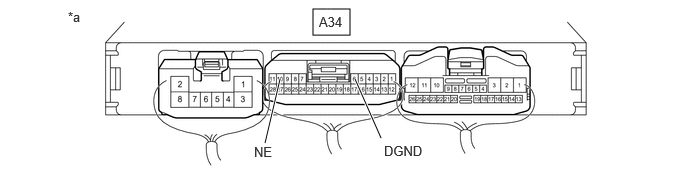
- Connect an oscilloscope to the NE and DGND terminals of the engine stop and start ECU connector.
*a Component with harness connected
(Engine Stop and Start ECU)- - - Start the engine.
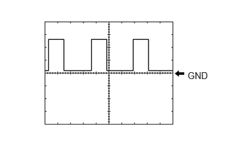
- Check the signal waveform according to the condition(s) in the table below.
Item Condition Tester Connection A34-10 (NE) - A34-6 (DGND) Tool Setting 5 V/DIV., 2 ms./DIV. Condition Idling with warm engine Result
Result Proceed to Pulse generation
(See waveform)A Stuck at 0 to 1.5 V B Stuck at 8 to 14 V C
Result:
A
REPLACE ENGINE STOP AND START ECU. Refer to REMOVAL [10/2022 - 11/2023]
Result:
C
GO TO ENGINE CONTROL SYSTEM. Refer to HOW TO PROCEED WITH TROUBLESHOOTING [10/2022 - ]
Result:
B
See step 6
- Connect an oscilloscope to the NE and DGND terminals of the engine stop and start ECU connector.
- CHECK ENGINE STOP AND START ECU (NE TERMINAL VOLTAGE)
- Disconnect the ECM connector.
*a Component with harness connected
(Engine Stop and Start ECU)- - - Turn the ignition switch to ON.
- Measure the voltage according to the value(s) in the table below.
Standard Voltage
Tester Connection Condition Specified Condition A34-10 (NE) - A34-6 (DGND) Ignition switch ON 8 to 14 V HINT:
DTCs may be stored during this inspection. Check for DTCs and clear them using the GTS.
Result
Proceed to OK NG
Result:
OK
GO TO ENGINE CONTROL SYSTEM. Refer to HOW TO PROCEED WITH TROUBLESHOOTING [10/2022 - ]
Result:
NG
REPLACE ENGINE STOP AND START ECU. Refer to REMOVAL [10/2022 - 11/2023]
- Disconnect the ECM connector.