Terminals Of Ecu [11/2023 - ]
NOTE:
- After turning the ignition switch to off, waiting time may be required before disconnecting the cable from the negative (-) auxiliary battery terminal. Therefore, make sure to read the disconnecting the cable from the negative (-) auxiliary battery terminal notices before proceeding with work.
Refer to PRECAUTION [11/2023 - ]
- When disconnecting the cable from the negative (-) auxiliary battery terminal while performing repairs, some systems need to be initialized after the cable is reconnected.
- When disconnecting and reconnecting the auxiliary battery.
HINT:
When disconnecting and reconnecting the auxiliary battery, there is an automatic learning function that completes learning when the respective system is used.
- CHECK POWER DISTRIBUTION BOX ASSEMBLY AND MAIN BODY ECU (MULTIPLEX NETWORK BODY ECU)
- Remove the main body ECU (multiplex network body ECU) from the power distribution box assembly.
Refer to REMOVAL [11/2023 - ]
- Reconnect the power distribution box assembly connectors.
Refer to INSTALLATION [11/2023 - ]
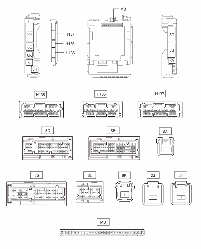
- Measure the voltage, resistance and check for pulses according to the value(s) in the table below.
Terminal No. (Symbol) Terminal Description Condition Specified Condition MB-13 (GND1) - Body ground Ground Always Below 1 Ω MB-14 (GND2) - Body ground Ground Always Below 1 Ω MB-26 (BECU) - Body ground Auxiliary battery power supply Always 11 to 14 V MB-27 (IGR) - Body ground IG power supply Ignition switch off Below 1 V Ignition switch ON 11 to 14 V MB-22 (CXP1) - Body ground CXPI communication line Ignition switch off Below 1 V Ignition switch ON Pulse generation - Install the main body ECU (multiplex network body ECU) to the power distribution box assembly.
Refer to INSTALLATION [11/2023 - ]
- Measure the voltage and check for pulses according to the value(s) in the table below.
Terminal No. (Symbol) Terminal Description Condition Specified Condition 8E-5 - Body ground CXPI communication line Ignition switch ON Pulse generation 8G-43 - Body ground Rear window defogger signal (output) Rear window defogger switch off Below 1.5 V Rear window defogger switch on 8 to 14 V 8E-18 - Body ground Taillight output Taillight not illuminated Below 1.5 V 8G-30 - Body ground 8B-2 - Body ground Mirror heater drive voltage (output) Rear window defogger switch off Below 1 V Rear window defogger switch on 11 to 14 V 8G-38 - Body ground Back-up light output Ignition switch ON, shift position is not R Below 1.5 V 8C-2 - Body ground Ignition switch ON, shift position is R 8 to 14 V 8G-22 - Body ground Panel illumination output Panel illumination not illuminated Below 1.5 V 8C-53 - Body ground Panel illumination illuminated 8 to 14 V
- Remove the main body ECU (multiplex network body ECU) from the power distribution box assembly.