Reassembly [12/2019 - 10/2022]: Procedure
- INSTALL FRONT DRIVE SHAFT BEARING (for AWD RH Side)
- INSTALL FRONT DRIVE SHAFT DUST COVER RH (for AWD RH Side)
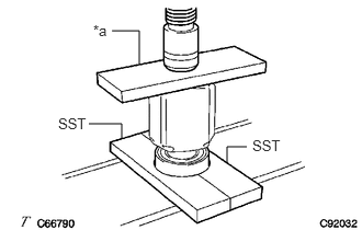
- Using a steel plate and a press, install a new front drive shaft dust cover RH until the dimension (A) from the tip of the front drive inboard joint assembly to the front drive shaft dust cover RH meets the specification.
Dimension (A)
341.7 to 342.3 mm (13.45 to 13.48 in.)
*a Steel Plate NOTE:Be careful not to damage the front drive shaft dust cover RH.
- Using a steel plate and a press, install a new front drive shaft dust cover RH until the dimension (A) from the tip of the front drive inboard joint assembly to the front drive shaft dust cover RH meets the specification.
- INSTALL FRONT AXLE OUTBOARD JOINT BOOT
- Secure the drive shaft in a vise between aluminum plates.NOTE:
Do not overtighten the vise.
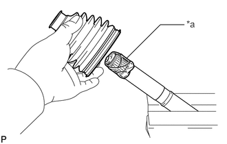
- Wrap the splines of the front drive outboard joint shaft assembly with protective tape to prevent the boot from being damaged.
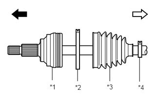
*a Protective Tape - Install new parts to the front drive outboard joint shaft assembly in the following order:
*1 Front Drive Outboard Joint Shaft Assembly *2 Front No. 2 Axle Outboard Joint Boot Clamp *3 Front Axle Outboard Joint Boot *4 Front Axle Outboard Joint Boot Clamp 
Outboard Joint Side 
Inboard Joint Side - Front No. 2 axle outboard joint boot clamp
- Front axle outboard joint boot
- Front axle outboard joint boot clamp
- Pack the joint portion of the front drive outboard joint shaft assembly and front axle outboard joint boot with grease.
Standard Grease Capacity
115 to 135 g (4.06 to 4.76 oz)
- Install the front axle outboard joint boot to the front drive outboard joint shaft assembly groove.NOTE:
- Do not allow grease to adhere to the boot clamp track of the outboard joint boot.
- Keep the inside of the outboard joint boot free of foreign matter.
- Secure the drive shaft in a vise between aluminum plates.
- INSTALL FRONT AXLE OUTBOARD JOINT BOOT CLAMP
- Secure the drive shaft in a vise between aluminum plates.NOTE:
Do not overtighten the vise.
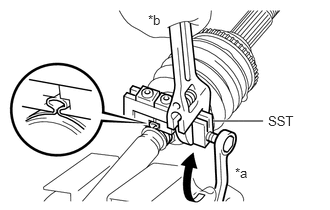
- Install the front axle outboard joint boot clamp to the front axle outboard joint boot.
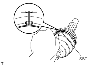
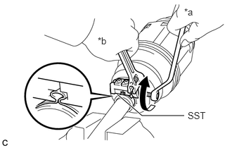
- Place SST to the front axle outboard joint boot clamp, press it against the boot and slightly tighten SST.
*a Turn *b Hold - SST: 09521-24010
- Tighten SST so that the front axle outboard joint boot clamp is pinched.NOTE:
Do not overtighten SST.
- Remove SST.
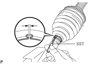
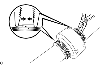
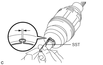
- Using SST, measure the clearance of the front axle outboard joint boot clamp.
- SST: 09240-00021
Clearance
1.2 to 4.0 mm (0.0472 to 0.1575 in.)
If the clearance is not as specified, retighten SST.
- Secure the drive shaft in a vise between aluminum plates.
- INSTALL FRONT NO. 2 AXLE OUTBOARD JOINT BOOT CLAMP
- Secure the drive shaft in a vise between aluminum plates.NOTE:
Do not overtighten the vise.
- Install the front No. 2 axle outboard joint boot clamp to the front axle outboard joint boot.
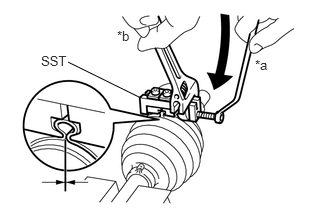
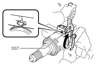
- Place SST onto the front No. 2 axle outboard joint boot clamp, press it against the boot and slightly tighten SST.
*a Turn *b Hold - SST: 09521-24010
- Tighten SST so that the front No. 2 axle outboard joint boot clamp is pinched.NOTE:
Do not overtighten SST.
- Remove SST.
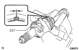
- Using SST, measure the clearance of the front No. 2 axle outboard joint boot clamp.
- SST: 09240-00021
Clearance
1.2 to 4.0 mm (0.0472 to 0.1575 in.)
If the clearance is not as specified, retighten SST.
- Secure the drive shaft in a vise between aluminum plates.
- INSTALL FRONT DRIVE SHAFT DAMPER
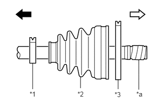
- Temporarily install the front drive shaft damper and 2 new front drive shaft damper clamps to the front drive outboard joint shaft assembly as shown in the illustration.
*1 Front Drive Shaft Damper Clamp *2 Front Drive Shaft Damper - Set the dimension (A) as specified below.
Dimension (A)
for LH Side 240.7 to 244.7 mm (9.48 to 9.63 in.) for RH Side 242.7 to 246.7 mm (9.56 to 9.71 in.)
- Temporarily install the front drive shaft damper and 2 new front drive shaft damper clamps to the front drive outboard joint shaft assembly as shown in the illustration.
- INSTALL FRONT DRIVE SHAFT DAMPER CLAMP
- INSTALL FRONT DRIVE INBOARD JOINT ASSEMBLY
- Install new parts to the front drive outboard joint shaft assembly in the following order:
*1 Front Axle Inboard Joint Boot Clamp *2 Front Axle Inboard Joint Boot *3 Front No. 2 Axle Inboard Joint Boot Clamp *a Protective Tape Outboard Joint Side Inboard Joint Side - Front axle inboard joint boot clamp
- Front axle inboard joint boot
- Front No. 2 axle inboard joint boot clamp
- Secure the drive shaft in a vise between aluminum plates.NOTE:
Do not overtighten the vise.
- Remove the protective tape.
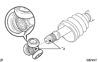
- Align the matchmarks and install the tripod joint to the front drive outboard joint shaft assembly.NOTE:
Face the serrated side of the tripod joint outward and install it to the outboard joint end.
*a Matchmark - Using a brass bar and a hammer, install the tripod joint to the front drive outboard joint shaft assembly.NOTE:
- Do not tap the rollers.
- Keep the tripod joint free of foreign matter.
- Be sure to install the tripod joint in the correct direction.
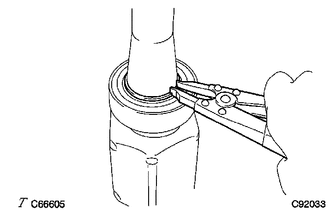
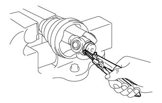
- Using a snap ring expander, install a new shaft snap ring to the front drive outboard joint shaft assembly.
- Pack the front drive inboard joint assembly and front axle inboard joint boot with grease.
Standard Grease Capacity
220 to 240 g (7.76 to 8.47 oz)
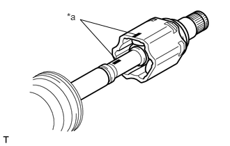
- Align the matchmarks and install the front drive inboard joint assembly to the front drive outboard joint shaft assembly.
*a Matchmark
- Install new parts to the front drive outboard joint shaft assembly in the following order:
- INSTALL FRONT AXLE INBOARD JOINT BOOT
- Install the front axle inboard joint boot to the front drive inboard joint assembly.
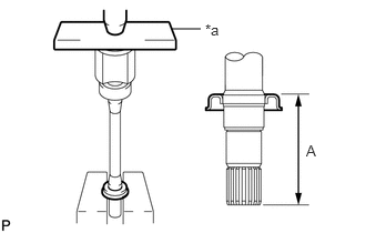
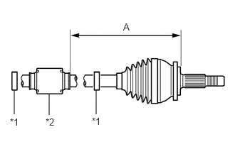
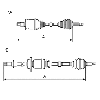
- Check whether the dimension (A) of each drive shaft is within the specification.NOTE:
Keep the drive shaft assembly level during inspection.
*A for LH Side *B for RH Side Dimension (A)
for LH Side 621.1 mm (2.04 ft.) for RH Side for 2WD 946.5 mm (3.10 ft.) for AWD 949 mm (3.11 ft.)
- INSTALL FRONT AXLE INBOARD JOINT BOOT CLAMP
- Secure the drive shaft in a vise between aluminum plates.NOTE:
Do not overtighten the vise.
- Install the front axle inboard joint boot clamp to the front axle inboard joint boot.
- Place SST onto the front axle inboard joint boot clamp, press it against the boot and slightly tighten SST.
- SST: 09521-24010
*a Turn *b Hold - Tighten SST so that the front axle inboard joint boot clamp is pinched.NOTE:
Do not overtighten SST.
- Remove SST.
- Using SST, measure the clearance of the front axle inboard joint boot clamp.
- SST: 09240-00021
Clearance
1.2 to 4.0 mm (0.0472 to 0.1575 in.)
If the clearance is not as specified, retighten SST.
- Secure the drive shaft in a vise between aluminum plates.
- INSTALL FRONT NO. 2 AXLE INBOARD JOINT BOOT CLAMP
- Secure the drive shaft in a vise between aluminum plates.NOTE:
Do not overtighten the vise.
- Install the front No. 2 axle inboard joint boot clamp to the front axle inboard joint boot.
- Place SST onto the front No. 2 axle inboard joint boot clamp, press it against the boot and slightly tighten SST.
*a Turn *b Hold - SST: 09521-24010
- Tighten SST so that the front No. 2 axle inboard joint boot clamp is pinched.NOTE:
Do not overtighten SST.
- Remove SST.
- Using SST, measure the clearance of the front No. 2 axle inboard joint boot clamp.
- SST: 09240-00021
Clearance
1.2 to 4.0 mm (0.0472 to 0.1575 in.)
If the clearance is not as specified, retighten SST.
- Secure the drive shaft in a vise between aluminum plates.
- INSPECT FRONT DRIVE SHAFT ASSEMBLY
See step 1