Reassembly [12/2019 - ]: Procedure
- INSTALL REAR DRIVE SHAFT OUTBOARD JOINT BOOT
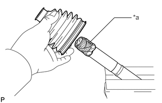
- Wrap the splines of the rear drive shaft outboard joint shaft assembly with protective tape to prevent the boot from being damaged.
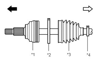
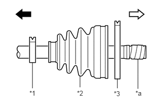
*a Protective Tape - Install new parts to the rear drive shaft outboard joint shaft assembly in the following order:
*1 Rear Drive Shaft Outboard Joint Shaft Assembly *2 Rear No. 2 Drive Shaft Outboard Joint Boot Clamp *3 Rear Drive Shaft Outboard Joint Boot *4 Rear Drive Shaft Outboard Joint Boot Clamp 
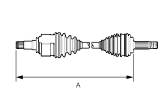
Outboard Joint Side 
Inboard Joint Side - Rear No. 2 drive shaft outboard joint boot clamp
- Rear drive shaft outboard joint boot
- Rear drive shaft outboard joint boot clamp
- Pack the joint portion of the rear drive shaft outboard joint shaft assembly and rear drive shaft outboard joint boot with grease.
Standard Grease Capacity
68 to 78 g (2.40 to 2.75 oz)
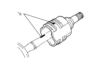
- Install the rear drive shaft outboard joint boot to the rear drive shaft outboard joint shaft assembly groove.NOTE:
- Do not allow grease to adhere to the boot clamp track of the outboard joint boot.
- Keep the inside of the outboard joint boot free of foreign matter.
- Wrap the splines of the rear drive shaft outboard joint shaft assembly with protective tape to prevent the boot from being damaged.
- INSTALL REAR NO. 2 DRIVE SHAFT OUTBOARD JOINT BOOT CLAMP
- Secure the drive shaft in a vise between aluminum plates.NOTE:
Do not overtighten the vise.
- Install the rear No. 2 drive shaft outboard joint boot clamp to the rear drive shaft outboard joint boot.
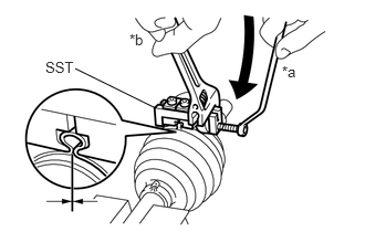
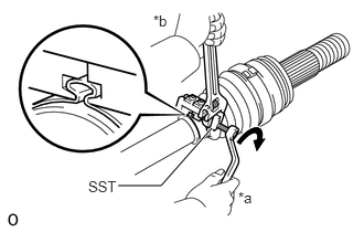
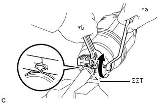
- Place SST onto the rear No. 2 drive shaft outboard joint boot clamp, press it against the boot and slightly tighten SST.
*a Turn *b Hold - SST: 09521-24010
- Tighten SST so that the rear No. 2 drive shaft outboard joint boot clamp is pinched.NOTE:
Do not overtighten SST.
- Remove SST.
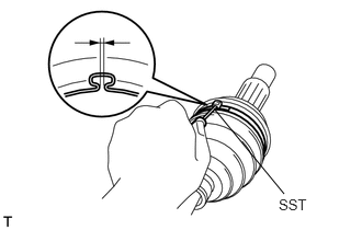
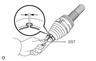
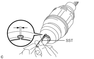
- Using SST, measure the clearance of the rear No. 2 drive shaft outboard joint boot clamp.
- SST: 09240-00021
Clearance
0 to 2.1 mm (0 to 0.0827 in.)
If the clearance is not as specified, retighten SST.
- Secure the drive shaft in a vise between aluminum plates.
- INSTALL REAR DRIVE SHAFT OUTBOARD JOINT BOOT CLAMP
- Secure the drive shaft in a vise between aluminum plates.NOTE:
Do not overtighten the vise.
- Install the rear drive shaft outboard joint boot clamp to the rear drive shaft outboard joint boot.
- Place SST onto the rear drive shaft outboard joint boot clamp, press it against the boot and slightly tighten SST.
*a Turn *b Hold - SST: 09521-24010
- Tighten SST so that the rear drive shaft outboard joint boot clamp is pinched.NOTE:
Do not overtighten SST.
- Remove SST.
- Using SST, measure the clearance of the rear drive shaft outboard joint boot clamp.
- SST: 09240-00021
Clearance
0 to 1.3 mm (0 to 0.0512 in.)
If the clearance is not as specified, retighten SST.
- Secure the drive shaft in a vise between aluminum plates.
- INSTALL REAR DRIVE SHAFT INBOARD JOINT ASSEMBLY
- Install new parts to the rear drive shaft outboard joint shaft assembly in the following order:
*1 Rear Drive Shaft Inboard Joint Boot Clamp *2 Rear Drive Shaft Inboard Joint Boot *3 Rear No. 2 Drive Shaft Inboard Joint Boot Clamp *a Protective Tape Outboard Joint Side Inboard Joint Side - Rear drive shaft inboard joint boot clamp
- Rear drive shaft inboard joint boot
- Rear No. 2 drive shaft inboard joint boot clamp
- Secure the drive shaft in a vise between aluminum plates.NOTE:
Do not overtighten the vise.
- Remove the protective tape.
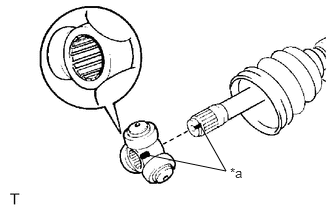
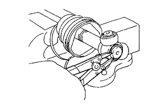
- Align the matchmarks and install the tripod joint to the rear drive shaft outboard joint shaft assembly.NOTE:
Face the serrated side of the tripod joint outward and install it to the outboard joint end.
*a Matchmark - Using a brass bar and a hammer, install the tripod joint to the rear drive shaft outboard joint shaft assembly.NOTE:
- Do not tap the rollers.
- Keep the tripod joint free of foreign matter.
- Be sure to install the tripod joint in the correct direction.
- Using a snap ring expander, install a new shaft snap ring to the rear drive shaft outboard joint shaft assembly.
- Pack the rear drive shaft inboard joint assembly and rear drive shaft inboard joint boot with grease.
Standard Grease Capacity
134 to 144 g (4.73 to 5.08 oz)
- Align the matchmarks and install the rear drive shaft inboard joint assembly to the rear drive shaft outboard joint shaft assembly.
*a Matchmark
- Install new parts to the rear drive shaft outboard joint shaft assembly in the following order:
- INSTALL REAR DRIVE SHAFT INBOARD JOINT BOOT
- INSTALL REAR NO. 2 DRIVE SHAFT INBOARD JOINT BOOT CLAMP
HINT:
Perform the same procedure as for the rear No. 2 drive shaft outboard joint boot clamp.
- INSTALL REAR DRIVE SHAFT INBOARD JOINT BOOT CLAMP
- Secure the drive shaft in a vise between aluminum plates.NOTE:
Do not overtighten the vise.
- Install the rear drive shaft inboard joint boot clamp to the rear drive shaft inboard joint boot.
- Place SST onto the rear drive shaft inboard joint boot clamp, press it against the boot and slightly tighten SST.
*a Turn *b Hold - SST: 09521-24010
- Tighten SST so that the rear drive shaft inboard joint boot clamp is pinched.NOTE:
Do not overtighten SST.
- Remove SST.
- Using SST, measure the clearance of the rear drive shaft inboard joint boot clamp.
- SST: 09240-00021
Clearance
0 to 1.3 mm (0 to 0.0512 in.)
If the clearance is not as specified, retighten SST.
- Secure the drive shaft in a vise between aluminum plates.
- INSPECT REAR DRIVE SHAFT ASSEMBLY
Refer to INSPECTION [12/2019 - ]