Installation [12/2019 - 10/2022]: Procedure
- TEMPORARILY TIGHTEN PROPELLER WITH CENTER BEARING SHAFT ASSEMBLY
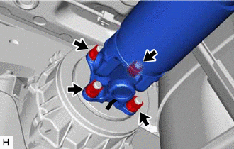
- When reusing a propeller with center bearing shaft assembly and rear differential carrier assembly:
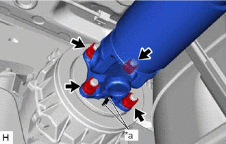
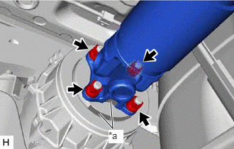
*a Matchmark - Align the matchmarks on the rear differential carrier assembly and propeller with center bearing shaft assembly.
- Temporarily install the 4 nuts and 4 washers.NOTE:
Do not apply grease to the 4 bolts, 4 nuts or 4 washers.
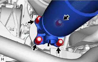
*a Alignment Mark When using a new propeller with center bearing shaft assembly or rear differential carrier assembly:
- Align the alignment marks on the rear differential carrier assembly and propeller with center bearing shaft assembly.
- Temporarily install the 4 nuts and 4 washers.NOTE:
Do not apply grease to the 4 bolts, 4 nuts or 4 washers.
- Align the matchmarks on the transfer assembly and propeller with center bearing shaft assembly.
*a Matchmark - Temporarily install the 4 nuts and 4 washers.NOTE:
Do not apply grease to the 4 bolts, 4 nuts or 4 washers.
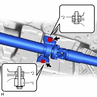
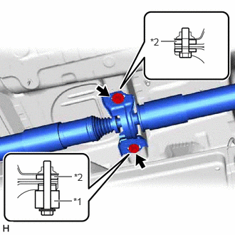
- Temporarily install the propeller with center bearing shaft assembly with the bolt, center support bearing damper and 2 center No. 2 support bearing washers (for front side).NOTE:
- Reuse the center No. 2 support bearing washers.
- Do not apply grease to the bolt, center support bearing damper and 2 center No. 2 support bearing washers.
*1 Center Support Bearing Damper *2 Center No. 2 Support Bearing Washer - Temporarily install the propeller with center bearing shaft assembly with the bolt, center support bearing damper and 2 center No. 2 support bearing washers (for rear side).NOTE:
- Reuse the center No. 2 support bearing washers.
- Do not apply grease to the bolt, center support bearing damper and 2 center No. 2 support bearing washers.
*1 Center Support Bearing Damper *2 Center No. 2 Support Bearing Washer - Fully tighten the 4 nuts.
Torque: 73.5 N.m (749 kgf/cm, 54 ft.lbf)
- Fully tighten the 4 nuts.
Torque: 73.5 N.m (749 kgf/cm, 54 ft.lbf)
- When reusing a propeller with center bearing shaft assembly and rear differential carrier assembly:
- FULLY TIGHTEN PROPELLER WITH CENTER BEARING SHAFT ASSEMBLY
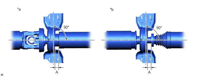
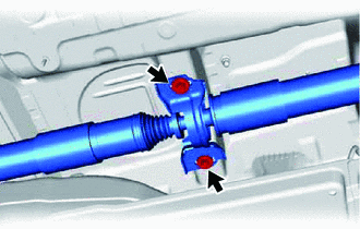
- With the vehicle unloaded, adjust the front and rear distance (A) between the edge surface of the center No. 2 support bearing assembly and the edge surface of the cushion respectively as shown in the illustration, and then tighten the bolts.
*a Center No. 2 Support Bearing Assembly (for Front Side) *b Center No. 2 Support Bearing Assembly (for Rear Side) Distance (A)
11.3 to 13.3 mm (0.445 to 0.524 in.)
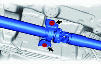
- Fully tighten the bolt and center support bearing damper (for front side).
Torque: 36.8 N.m (375 kgf/cm, 27 ft.lbf)
- Fully tighten the bolt and center support bearing damper (for rear side).
Torque: 36.8 N.m (375 kgf/cm, 27 ft.lbf)
- Check that the center line of the bracket is at a right angle to the shaft axial direction.
- With the vehicle unloaded, adjust the front and rear distance (A) between the edge surface of the center No. 2 support bearing assembly and the edge surface of the cushion respectively as shown in the illustration, and then tighten the bolts.
- INSPECT AND ADJUST JOINT ANGLE NOTE:
Measure the joint angle when the vehicle is raised using a four-post lift or when using a pit.
HINT:
If any vibration or noise occurs, perform the joint angle check as follows and replace the center No. 2 support bearing washers with ones of the correct thickness.
- Stabilize the propeller shaft and differential.
- Turn the propeller shaft several times by hand to stabilize the center support bearings.
- Using a jack, raise and lower the differential to stabilize the differential mounting cushion.
- Check the joint angles.
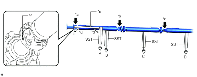
- Check the No. 1, No. 2 and No. 3 joint angles.
*a No. 1 Joint Angle (A - B) *b No. 2 Joint Angle (B - C) *c No. 3 Joint Angle (C - D) *d 90° *e Straightedge *f Straightedge Contact Position - Using SST, measure the transfer assembly installation angle (A) and propeller shaft assembly installation angle (B), (C) and (D).
- SST: 09370-50010
Joint Angle
Measurement Position Joint Angle for Dynamic Torque Control AWD for Dynamic Torque Vectoring AWD No. 1 Joint Angle (A - B) -2.33° +/- 1.00° -2.33° +/- 1.00° No. 2 Joint Angle (B - C) 0.72° +/- 1.00° 0.71° +/- 1.00° No. 3 Joint Angle (C - D) 0.15° +/- 1.00° 0.31° +/- 1.00° - Check the No. 4 joint angle.
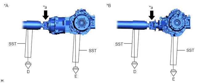
*A for Dynamic Torque Control AWD *B for Dynamic Torque Vectoring AWD *a No. 4 Joint Angle (D - E) - - - Using SST, measure the rear propeller shaft assembly installation angle (D) and rear differential carrier assembly installation angle (E).
- SST: 09370-50010
Joint Angle
Measurement Position Joint Angle for Dynamic Torque Control AWD for Dynamic Torque Vectoring AWD No. 4 Joint Angle (D - E) 1.86° +/- 1.00° 1.68° +/- 1.00° If the measured angle is not within the specified range, adjust it with center No. 2 support bearing washers.
- Check the No. 1, No. 2 and No. 3 joint angles.
- Adjust the No. 1 joint angle and No. 4 joint angle.
- Select center No. 2 support bearing washers for adjustment.
Center No. 2 Support Bearing Washer Thickness
Part No. Thickness mm (in.) 90201-10123 2.0 mm (0.079 in.) 90201-10081 4.5 mm (0.177 in.) 90201-10083 6.5 mm (0.256 in.) 90201-10084 9.0 mm (0.354 in.) NOTE:- Make sure to use center No. 2 support bearing washers of the same thickness on both the right and left sides.
- Do not use more than 1 adjusting washer per bolt.
- Select center No. 2 support bearing washers for adjustment.
- Stabilize the propeller shaft and differential.
- INSTALL REAR MAIN MUFFLER HEAT INSULATOR SUB-ASSEMBLY
- Install the rear main muffler heat insulator sub-assembly to the vehicle body with the 3 bolts and 2 nuts.
Bolt
Torque: 7.5 N.m (76 kgf/cm, 66 in.lbf)
Nut
Torque: 4.9 N.m (50 kgf/cm, 43 in.lbf)
- Install the No. 3 exhaust pipe support bracket and No. 4 exhaust pipe support bracket with the 4 bolts.
Torque: 29 N.m (296 kgf/cm, 21 ft.lbf)
- Install the rear main muffler heat insulator sub-assembly to the vehicle body with the 3 bolts and 2 nuts.
- INSTALL ENGINE SERVICE COVER ASSEMBLY
- Install the engine service cover assembly to the vehicle body with the 6 bolts and 3 nuts.
Bolt
Torque: 7.5 N.m (76 kgf/cm, 66 in.lbf)
Nut
Torque: 4.9 N.m (50 kgf/cm, 43 in.lbf)
- Install the No. 1 exhaust pipe support bracket with the 2 bolts.
Torque: 29 N.m (296 kgf/cm, 21 ft.lbf)
- Install the engine service cover assembly to the vehicle body with the 6 bolts and 3 nuts.
- INSTALL CENTER EXHAUST PIPE ASSEMBLY (TWC: Rear Catalyst)
Refer to PROCEDURE - Step 4
- INSTALL TAIL EXHAUST PIPE ASSEMBLY
Refer to PROCEDURE - Step 5
- INSPECT FOR EXHAUST GAS LEAK
Refer to PROCEDURE - Step 6
- PERFORM INITIALIZATION
- SFI system initialization:
Refer to INITIALIZATION [12/2019 - 10/2022]
- SFI system initialization: