On-Vehicle Inspection [12/2019 - ]: Procedure
- INSPECT BRAKE PEDAL LOAD SENSING SWITCH (BRAKE PEDAL SUPPORT ASSEMBLY)
- Make sure that there is no looseness in the locking part and the connecting part of the connector.
- Disconnect the brake pedal load sensing switch (brake pedal support assembly) connector.
- Check both the connector case and the terminal for deformation and corrosion.
OK
No deformation or corrosion.
NOTE:- Do not remove the brake pedal load sensing switch from the brake pedal support assembly.
- When there is a malfunction in the brake pedal load sensing switch, replace the brake pedal support assembly.
- Measure the resistance according to the value(s) in the table below.
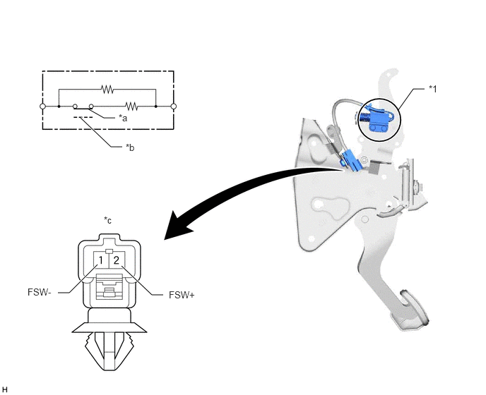
*1 Brake Pedal Load Sensing Switch - - *a Brake pedal released (ON) *b Brake pedal depressed (OFF) *c Component without harness connected
(Brake Pedal Load Sensing Switch)- - Standard Resistance
Tester Connection Condition Specified Condition 1 (FSW-) - 2 (FSW+) Brake pedal load sensing switch off (Brake pedal depressed) 950 to 1050 Ω Brake pedal load sensing switch on (Brake pedal released) 203 to 223 Ω If the result is not as specified, replace the brake pedal support assembly.