Terminals Of Ecu [12/2019 - 11/2023]
- CHECK POSITION CONTROL ECU ASSEMBLY
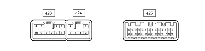
- Disconnect the e23 and e25 position control ECU assembly connectors.
- Measure the voltage and resistance according to the value(s) in the table below.
HINT:
Measure the values on the wire harness side with the connector disconnected.
Tester Connection Terminal Description Condition Specified Condition e23-3 (+B) - Body ground Auxiliary battery power supply Ignition switch off*1
Always*211 to 14 V e25-1 (IG) - Body ground Ignition power supply Ignition switch off Below 1 V Ignition switch ON 11 to 14 V e25-15 (SYSB) - Body ground System power source Ignition switch off*1
Always*211 to 14 V e23-2 (GND) - Body ground Ground Always Below 1 Ω - *1: for HV Model
- *2: for Gasoline Model
- Reconnect the e23 and e25 position control ECU assembly connectors.
- Measure the voltage and resistance according to the value (s) in the table below.
Tester Connection Terminal Description Condition Specified Condition e23-1 (SLD+) - Body ground Slide motor signal (forward) Slide switch off Below 1 V Slide switch on (Forward) 11 to 14 V e23-5 (SLD-) - Body ground Slide motor signal (rearward) Slide switch off Below 1 V Slide switch on (Rearward) 11 to 14 V e23-6 (LFT+) - Body ground Lifter motor signal (upward) Lifter switch off Below 1 V Lifter switch on (Upward) 11 to 14 V e24-5 (LFT-) - Body ground Lifter motor signal (downward) Lifter switch off Below 1 V Lifter switch on (Downward) 11 to 14 V e23-10 (RCL+) - Body ground Reclining motor signal (forward) Reclining switch off Below 1 V Reclining switch on (Forward) 11 to 14 V e24-6 (RCL-) - Body ground Reclining motor signal (rearward) Reclining switch off Below 1 V Reclining switch on (Rearward) 11 to 14 V e23-7 (FRV+) - Body ground Front vertical motor signal (upward) Front vertical switch off Below 1 V Front vertical switch on (Upward) 11 to 14 V e24-4 (FRV-) - Body ground Front vertical motor signal (downward) Front vertical switch off Below 1 V Front vertical switch on (Downward) 11 to 14 V e23-9 (L+) - Body ground Lumbar support adjuster motor signal (forward) Lumbar support adjuster switch off Below 1 V Lumbar support adjuster switch on (Forward) 11 to 14 V e24-3 (L-) - Body ground Lumbar support adjuster motor signal (rearward) Lumbar support adjuster switch off Below 1 V Lumbar support adjuster switch on (Rearward) 11 to 14 V e25-4 (LFLF) - Body ground Front power seat switch LH (lumbar support adjuster switch (forward)) signal Lumbar support adjuster switch off 11 to 14 V Lumbar support adjuster switch on (Forward) Below 1 V e25-18 (LFLR) - Body ground Front power seat switch LH (lumbar support adjuster switch (rearward)) signal Lumbar support adjuster switch off 11 to 14 V Lumbar support adjuster switch on (Rearward) Below 1 Ω e25-9 (SLDF) - Body ground Front power seat switch LH (slide switch (forward)) signal Slide switch off 11 to 14 V Slide switch on (Forward) Below 1 V e25-23 (SLDR) - Body ground Front power seat switch LH (slide switch (rearward)) signal Slide switch off 11 to 14 V Slide switch on (Rearward) Below 1 V e25-8 (RCLF) - Body ground Front power seat switch LH (reclining switch (forward)) signal Reclining switch off 11 to 14 V Reclining switch on (Forward) Below 1 V e25-22 (RCLR) - Body ground Front power seat switch LH (reclining switch (rearward)) signal Reclining switch off 11 to 14 V Reclining switch on (Rearward) Below 1 V e25-6 (FRVU) - Body ground Front power seat switch LH (front vertical switch (upward)) signal Front vertical switch off 11 to 14 V Front vertical switch on (Upward) Below 1 V e25-20 (FRVD) - Body ground Front power seat switch LH (front vertical switch (downward)) signal Front vertical switch off 11 to 14 V Front vertical switch on (Downward) Below 1 V e25-7 (LFTU) - Body ground Front power seat switch LH (lifter switch (upward)) signal Lifter switch off 11 to 14 V Lifter switch on (Upward) Below 1 V e25-21 (LFTD) - Body ground Front power seat switch LH (lifter switch (downward)) signal Lifter switch off 11 to 14 V Lifter switch on (Downward) Below 1 V e25-10 (SSFV) - Body ground Front vertical position signal Front vertical function operating 4.8 to 5.1 V e25-11 (SSRR) - Body ground Reclining position signal Reclining function operating 4.8 to 5.1 V e25-25 (SSRL) - Body ground Lifter position signal Lifter function operating 4.8 to 5.1 V e25-26 (SSRS) - Body ground Slide position signal Slide function operating 4.8 to 5.1 V e25-12 (SGND) - Body ground Sensor ground Always Below 1 Ω
- CHECK OUTER MIRROR CONTROL ECU ASSEMBLY (DRIVER DOOR)
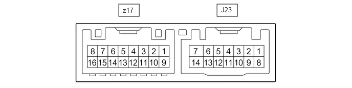
- Disconnect the J23 outer mirror control ECU assembly (driver door) connector.
- Measure the voltage and resistance according to the value (s) in the table below.
HINT:
Measure the values on the wire harness side with the connector disconnected.
Tester Connection Terminal Description Condition Specified Condition J23-6 (CPUB) - J23-7 (GND) Auxiliary battery power supply Ignition switch off*1
Always*211 to 14 V J23-14 (BDR) - J23-7 (GND) Auxiliary battery power supply Ignition switch off*1
Always*211 to 14 V J23-5 (SIG) - J23-7 (GND) Ignition power supply Ignition switch ON 11 to 14 V J23-5 (SIG) - J23-7 (GND) Ignition power supply Ignition switch off Below 1 V J23-7 (GND) - Body ground Ground Always Below 1 Ω - *1: for HV Model
- *2: for Gasoline Model
- Reconnect the J23 outer mirror control ECU assembly (driver door) connector.
- Measure the voltage according to the value (s) in the table below.
Tester Connection Terminal Description Condition Specified Condition J23-1 (MM) - J23-7 (GND) SET switch signal for seat memory switch SET switch on Below 1 V SET switch off 11 to 14 V J23-2 (M1) - J23-7 (GND) M1 switch signal for seat memory switch M1 switch on Below 1 V M1 switch off 11 to 14 V J23-3 (M2) - J23-7 (GND) M2 switch signal for seat memory switch M2 switch on Below 1 V M2 switch off 11 to 14 V
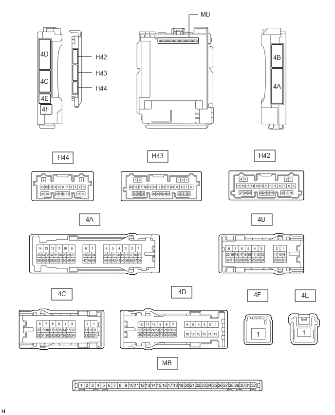
- CHECK MAIN BODY ECU (MULTIPLEX NETWORK BODY ECU) AND INSTRUMENT PANEL JUNCTION BLOCK ASSEMBLY
- Remove the main body ECU (multiplex network body ECU) from the instrument panel junction block assembly.
Refer to REMOVAL [12/2019 - 10/2022] , or refer to REMOVAL [10/2022 - 11/2023]
- Measure the voltage and resistance according to the value (s) in the table below.
HINT:
Measure the values on the wire harness side with the connector disconnected.
Tester Connection Terminal Description Condition Specified Condition MB-31 (BECU) - Body ground Auxiliary battery power supply Ignition switch off*1
Always*211 to 14 V MB-32 (IG) - Body ground Ignition power supply Ignition switch ON 11 to 14 V MB-32 (IG) - Body ground Ignition power supply Ignition switch off Below 1 V MB-30 (ACC) - Body ground Ignition power supply Ignition switch ACC 11 to 14 V MB-30 (ACC) - Body ground Ignition power supply Ignition switch off Below 1 V MB-11 (GND1) - Body ground Ground Always Below 1 Ω H43-1 (FLCY) - Body ground Front door courtesy light switch assembly (driver door) input Front door LH closed (OFF) → open (ON) 10 kΩ or higher → Below 1 Ω - *1: for HV Model
- *2: for Gasoline Model
- Remove the main body ECU (multiplex network body ECU) from the instrument panel junction block assembly.