Terminals Of Ecu [12/2019 - 11/2023]
- CHECK AIR CONDITIONING AMPLIFIER ASSEMBLY
 Courtesy of © TOYOTA, LICENSE AGREEMENT TMS1002
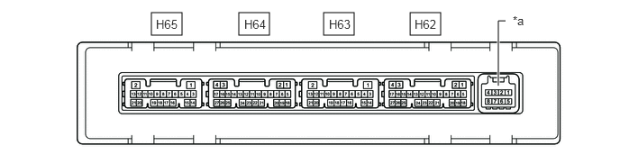
*a This connector is not used by the climate control seat system. Refer to Air Conditioning System. - - - Disconnect the H62 air conditioning amplifier assembly connector.
- Measure the voltage and resistance according to the value(s) in the table below.
HINT:
Measure the values on the wire harness side with the connector disconnected.
Terminal No. (Symbol) Terminal Description Condition Specified Condition H62-6 (IG+) - H62-17 (GND) IG power supply Ignition switch off Below 1 V H62-6 (IG+) - H62-17 (GND) IG power supply Ignition switch ON 11 to 14 V H62-5 (B) - H62-17 (GND) Auxiliary battery power supply Ignition switch off*1
Always*211 to 14 V H62-17 (GND) - Body ground Ground Always Below 1 Ω - *1: for HV Model
- *2: for Gasoline Model
- Reconnect the H62 air conditioning amplifier assembly connector.
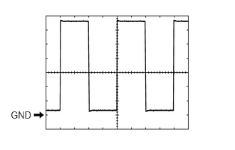
- Check for pulses according to the value(s) in the table below.
Terminal No. (Symbol) Terminal Description Condition Specified Condition H62-14 (LOUT) - Body ground Climate control blower control signal - Ignition switch ON
- Climate control switch (Air conditioning control assembly) (for LH) on (blower position)
Pulse generation
(See waveform)H62-13 (ROUT) - Body ground Climate control blower control signal - Ignition switch ON
- Climate control switch (Air conditioning control assembly) (for RH) on (blower position)
Pulse generation
(See waveform)H62-7 (LIN1) - Body ground Climate control switch signal Ignition switch ON Pulse generation
- CLIMATE CONTROL SWITCH (AIR CONDITIONING CONTROL ASSEMBLY)
- Disconnect the H27 Climate control switch (Air conditioning control assembly) connector.
- Measure the voltage and resistance according to the value(s) in the table below.
HINT:
Measure the values on the wire harness side with the connector disconnected.
Terminal No. (Symbol) Terminal Description Condition Specified Condition H27-4 (IG+) - H27-8 (E)*1 IG power supply Ignition switch off Below 1 V H27-6 (IG+) - H27-10 (GND)*2 H27-4 (IG+) - H27-8 (E)*1 IG power supply Ignition switch ON 11 to 14 V H27-6 (IG+) - H27-10 (GND)*2 H27-8 (E) - Body ground*1 Ground Always Below 1 Ω H27-10 (GND) - Body ground*2 - *1: for 12.3 Inch Display
- *2: for 8 Inch Display
- Reconnect the H27 Climate control switch (Air conditioning control assembly) connector.
- Check for pulses according to the value(s) in the table below.
Terminal No. (Symbol) Wiring Color Terminal Description Condition Specified Condition H27-3 (LIN1) - H27-8 (E)*1 B - Body ground Climate control switch signal Ignition switch ON Pulse generation H27-8 (LIN1) - H27-10 (GND)*2 - *1: for 12.3 Inch Display
- *2: for 8 Inch Display