Terminals Of Ecu [11/2023 - ]
- CHECK OUTER MIRROR CONTROL ECU ASSEMBLY (DRIVER DOOR)
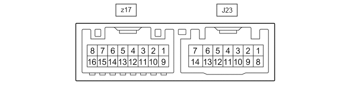
- Disconnect the J23 outer mirror control ECU assembly (driver door) connector.
- Measure the voltage and resistance according to the value(s) in the table below.
Terminal No. (Symbol) Terminal Description Condition Specified Condition J23-14 (BDR) - Body ground +B power supply Ignition switch off*1
Always*211 to 14 V J23-6 (CPUB) - Body ground +B power supply Ignition switch off*1
Always*211 to 14 V J23-5 (SIG) - Body ground Ignition power supply Ignition switch off → ON Below 1 V → 11 to 14 V J23-7 (GND) - Body ground Ground Always Below 1 Ω - *1: for HV Model
- *2: for Gasoline Model
- Reconnect the J23 outer mirror control ECU assembly (driver door) connector.
- Measure the voltage according to the value(s) in the table below.
Terminal No. (Symbol) Terminal Description Condition Specified Condition z17-3 (MR) - Body ground Power retract mirror motor drive voltage Outer rear view mirror assembly (driver door) being retracted 11 to 14 V Outer rear view mirror assembly (driver door) stopped Below 1 V z17-11 (MF) - Body ground Power retract mirror motor drive voltage Outer rear view mirror assembly (driver door) returning 11 to 14 V Outer rear view mirror assembly (driver door) stopped Below 1 V z17-1 (MV) - z17-10 (M+) Vertical mirror motor drive voltage Driver door mirror surface moving upward → stopped 11 to 14 V → Below 1 V z17-10 (M+) - z17-1 (MV) Vertical mirror motor drive voltage Driver door mirror surface moving downward → stopped 11 to 14 V → Below 1 V z17-10 (M+) - z17-9 (MH) Horizontal mirror motor drive voltage Driver door mirror surface moving right → stopped 11 to 14 V → Below 1 V z17-9 (MH) - z17-10 (M+) Horizontal mirror motor drive voltage Driver door mirror surface moving left → stopped 11 to 14 V → Below 1 V z17-5 (VC) - z17-14 (E1) Mirror position sensor power supply Ignition switch ON 4.55 to 5.45 V Ignition switch off Below 1 V z17-6 (VSRL) - J23-7 (GND) Mirror position sensor signal Ignition switch ON 0 to 5 V z17-13 (HSRL) - J23-7 (GND) Mirror position sensor signal Ignition switch ON 0 to 5 V J23-3 (M2) - J23-7 (GND) M2 switch signal for seat memory switch M2 switch on Below 1 V M2 switch off 11 to 14 V J23-2 (M1) - J23-7 (GND) M1 switch signal for seat memory switch M1 switch on Below 1 V M1 switch off 11 to 14 V J23-1 (MM) - J23-7 (GND) SET switch signal for seat memory switch SET switch on Below 1 V SET switch off 11 to 14 V z17-4 (+) - z17-12 (-) Mirror heater relay drive voltage Mirror heater switch (rear window defogger switch) on 11 to 14 V z17-2 (MLP+) - z17-12 (-) Foot light drive output Foot light off → on Below 1 V → 11 to 14 V
- CHECK OUTER MIRROR CONTROL ECU ASSEMBLY (FRONT PASSENGER DOOR)
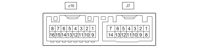
- Disconnect the J7 outer mirror control ECU assembly (front passenger door) connector.
- Measure the voltage and resistance according to the value(s) in the table below.
Terminal No. (Symbol) Terminal Description Condition Specified Condition J7-14 (BDR) - Body ground +B power supply Ignition switch off*1
Always*211 to 14 V J7-6 (CPUB) - Body ground +B power supply Ignition switch off*1
Always*211 to 14 V J7-5 (SIG) - Body ground Ignition power supply Ignition switch off → ON Below 1 V → 11 to 14 V J7-7 (GND) - Body ground Ground Always Below 1 Ω - *1: for HV Model
- *2: for Gasoline Model
- Reconnect the J7 outer mirror control ECU assembly (front passenger door) connector.
- Measure the voltage according to the value(s) in the table below.
Terminal No. (Symbol) Terminal Description Condition Specified Condition z16-3 (MR) - Body ground Power retract mirror motor drive voltage Outer rear view mirror assembly (front passenger door) being retracted 11 to 14 V Outer rear view mirror assembly (front passenger door) stopped Below 1 V z16-11 (MF) - Body ground Power retract mirror motor drive voltage Outer rear view mirror assembly (front passenger door) returning 11 to 14 V Outer rear view mirror assembly (front passenger door) stopped Below 1 V z16-1 (MV) - z16-10 (M+) Vertical mirror motor drive voltage Front passenger door mirror surface moving upward → stopped 11 to 14 V → Below 1 V z16-10 (M+) - z16-1 (MV) Vertical mirror motor drive voltage Front passenger door mirror surface moving downward → stopped 11 to 14 V → Below 1 V z16-10 (M+) - z16-9 (MH) Horizontal mirror motor drive voltage Front passenger door mirror surface moving right → stopped 11 to 14 V → Below 1 V z16-9 (MH) - z16-10 (M+) Horizontal mirror motor drive voltage Front passenger door mirror surface moving left → stopped 11 to 14 V → Below 1 V z16-5 (VC) - z16-14 (E1) Mirror position sensor power supply Ignition switch ON 4.55 to 5.45 V Ignition switch off Below 1 V z16-6 (VSSR) - J7-7 (GND) Mirror position sensor signal Ignition switch ON 0 to 5 V z16-13 (HSSR) - J7-7 (GND) Mirror position sensor signal Ignition switch ON 0 to 5 V z16-4 (+) - z16-12 (-) Mirror heater relay drive voltage Mirror heater switch (rear window defogger switch) on 11 to 14 V z16-2 (MLP+) - z16-12 (-) Foot light drive output Foot light off → on Below 1 V → 11 to 14 V
- CHECK MAIN BODY ECU (MULTIPLEX NETWORK BODY ECU) AND POWER DISTRIBUTION BOX ASSEMBLY
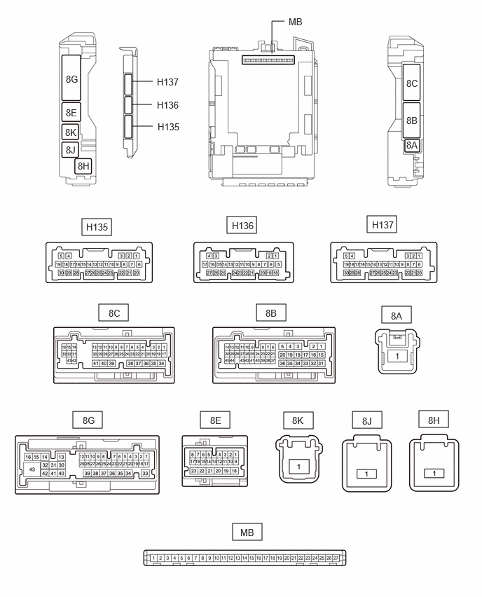
- Disconnect the power distribution box assembly and main body ECU (multiplex network body ECU) connectors.
Refer to REMOVAL [11/2023 - ]
- Reconnect the power distribution box assembly connectors.
- Measure the resistance and voltage according to the value(s) in the table below.
Terminal No. (Symbol) Terminal Description Condition Specified Condition MB-26 (BECU) - Body ground Auxiliary battery power supply Ignition switch off*1
Always*211 to 14 V MB-27 (IGR) - Body ground Ignition power supply (IG signal) Ignition switch ON 11 to 14 V Ignition switch off Below 1 V MB-13 (GND1) - Body ground Ground Always Below 1 Ω - *1: for HV Model
- *2: for Gasoline Model
- Connect the main body ECU (multiplex network body ECU) connectors.
- Measure the voltage according to the value(s) in the table below.
Tester Connection Terminal Description Condition Specified Condition H137-22 (MIRB) - H137-21 (MIRE) Mirror adjust switch signal - Ignition switch ACC
- Mirror select switch L or R
- Mirror adjust switch up
Below 1.7 V - Ignition switch ACC
- Mirror select switch L or R
- Mirror adjust switch right
Below 2.7 V - Ignition switch ACC
- Mirror select switch L or R
- Mirror adjust switch down
Below 3.5 V - Ignition switch ACC
- Mirror select switch L or R
- Mirror adjust switch left
Below 4 V - Ignition switch ACC
- Mirror select switch L or R
- Mirror adjust switch off
11 to 14 V H137-20 (MIRS) - H137-21 (MIRE) Mirror select switch signal - Ignition switch ACC
- Mirror select switch L
Below 2 V - Ignition switch ACC
- Mirror select switch R
Below 1 V - Ignition switch ACC
- Mirror select switch off
11 to 14 V H136-27 (RET) - H137-21 (MIRE) Retractable outer mirror switch signal - Ignition switch ACC
- Retractable outer mirror switch not in retract position
11 to 14 V - Ignition switch ACC
- Retractable outer mirror switch in retract position
Below 1 V H136-26 (AMR) - H137-21 (MIRE) Retractable outer mirror switch signal - Ignition switch ACC
- Retractable outer mirror switch not in auto position
11 to 14 V - Ignition switch ACC
- Retractable outer mirror switch in auto position
Below 1 V
- Disconnect the power distribution box assembly and main body ECU (multiplex network body ECU) connectors.