Grille Shutter does not Operate [10/2021 - ]: Procedure
- PERFORM UTILITY USING GTS (SWITCH GRILLE SHUTTER CONTROL MODE)
- According to the display on the GTS, change the grille shutter control mode from normal mode to maintenance mode.
Powertrain > Engine > Utility
Tester Display Switch Grille Shutter Control Mode Result
Proceed to NEXT
Result:
NEXT
See step 2
- According to the display on the GTS, change the grille shutter control mode from normal mode to maintenance mode.
- CHECK FOR GRILLE SHUTTER (FOREIGN MATTER AND ICE)
- Check the area around the shutters and the links of the grille shutter for foreign matter and ice.
OK
The radiator shutter sub-assembly is free of foreign matter and ice.
Result
Proceed to OK NG
Result:
NG
See step 10
Result:
OK
See step 3
- Check the area around the shutters and the links of the grille shutter for foreign matter and ice.
- CHECK RADIATOR SHUTTER ASSEMBLY (GRILLE SHUTTER OPERATION)
- Remove the radiator shutter assembly.
Refer to REMOVAL [10/2021 - ]
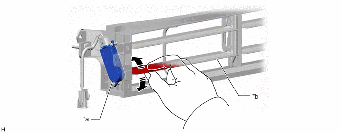
- While using fingers to pinch the fin at the location shown in the illustration, fully open and close the radiator shutter assembly manually and check that it moves smoothly.
HINT:
If the fin is pinched with fingers far from the swing grille actuator assembly, the function may not be able to be inspected correctly.
*a Swing Grille Actuator Assembly *b Fin OK
Radiator shutter sub-assembly moves smoothly.
- Install the radiator shutter assembly.
Refer to INSTALLATION [10/2021 - ]
Result
Proceed to OK NG
Result:
NG
REPLACE RADIATOR SHUTTER ASSEMBLY
Refer to REMOVAL [10/2021 - ]
Result:
OK
See step 4
- Remove the radiator shutter assembly.
- CLEAR DTC
- Clear the DTCs.
Powertrain > Engine > Clear DTCs
- Turn the ignition switch off and wait for at least 30 seconds.
Result
Proceed to NEXT
Result:
NEXT
See step 5
- Clear the DTCs.
- CHECK DTC
- Check for DTCs.
Powertrain > Engine > Trouble Codes
Result
Result Proceed to DTCs are not output. OK DTCs are output. NG
Result:
NG
GO TO SFI SYSTEM (DIAGNOSTIC TROUBLE CODE CHART)
Refer to DIAGNOSTIC TROUBLE CODE CHART [10/2021 - 10/2022] , or refer to DIAGNOSTIC TROUBLE CODE CHART [10/2022 - 11/2023] , or refer to DIAGNOSTIC TROUBLE CODE CHART [11/2023 - 11/2024] , or refer to DIAGNOSTIC TROUBLE CODE CHART [11/2024 - ]
Result:
OK
See step 6
- Check for DTCs.
- CHECK HARNESS AND CONNECTOR (SWING GRILLE ACTUATOR ASSEMBLY - POWER SUPPLY AND BODY GROUND)
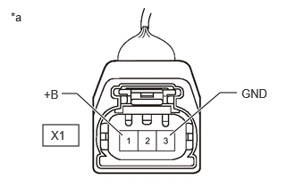
- Disconnect the X1 swing grille actuator assembly connector.
*a Front view of wire harness connector
(to Swing Grille Actuator Assembly) - Measure the voltage according to the value(s) in the table below.
Standard Voltage
Tester Connection Condition Specified Condition X1-1 (+B) - Body ground Ignition switch ON 11 to 14 V - Measure the resistance according to the value(s) in the table below.
Standard Resistance
Tester Connection Condition Specified Condition X1-3 (GND) - Body ground Always Below 1 Ω - Connect the X1 swing grille actuator assembly connector.
Result
Proceed to OK NG
Result:
NG
See step 8
Result:
OK
See step 7
- Disconnect the X1 swing grille actuator assembly connector.
- READ VALUE USING GTS (GRILLE SHUTTER CONTROL MODE)
- According to the display on the GTS, change the grille shutter control mode from maintenance mode to normal mode.
Powertrain > Engine > Utility
Tester Display Switch Grille Shutter Control Mode - Read the value displayed on the GTS.
Powertrain > Engine > Data List
Tester Display Measurement Item Range Normal Condition Diagnostic Note Grille Shutter Control Mode Grille shutter control mode status Normal or Maintenance Normal: Normal mode
Maintenance: Maintenance mode- Powertrain > Engine > Data List
Tester Display Grille Shutter Control Mode OK
Normal is displayed.
Result
Proceed to NEXT
Result:
NEXT
END
HINT:
Operation temporarily abnormal due to fail-safe (abnormal temperature).
- According to the display on the GTS, change the grille shutter control mode from maintenance mode to normal mode.
- CHECK HARNESS AND CONNECTOR (SWING GRILLE ACTUATOR ASSEMBLY - EFI-MAIN NO. 1 RELAY)
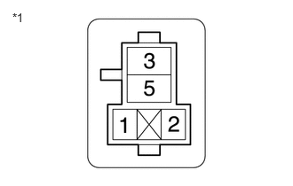
- Remove the EFI-MAIN NO. 1 relay from the No. 1 engine room relay block and No. 1 junction block assembly.
*1 No. 1 Engine Room Relay Block and No. 1 Junction Block Assembly
(EFI-MAIN NO. 1 Relay Holder) - Disconnect the X1 swing grille actuator assembly connector.
- Measure the resistance according to the value(s) in the table below.
Standard Resistance
Tester Connection Condition Specified Condition X1-1 (+B) - No. 1 engine room relay block and No. 1 junction block assembly EFI-MAIN NO. 1 relay terminal 5 Always Below 1 Ω X1-1 (+B) or No. 1 engine room relay block and No. 1 junction block assembly EFI-MAIN NO. 1 relay terminal 5 - Body ground Always 10 kΩ or higher - Install the EFI-MAIN NO. 1 relay from the No. 1 engine room relay block and No. 1 junction block assembly.
- Connect the X1 swing grille actuator assembly connector.
Result
Proceed to OK NG
Result:
NG
REPAIR OR REPLACE HARNESS OR CONNECTOR
Result:
OK
See step 9
- Remove the EFI-MAIN NO. 1 relay from the No. 1 engine room relay block and No. 1 junction block assembly.
- CHECK ECM POWER SOURCE CIRCUIT
- Check the ECM power source circuit.
Refer to ECM Power Source Circuit [12/2019 - 11/2023] , or refer to ECM Power Source Circuit [11/2023 - ]
Result
Proceed to NEXT
Result:
NEXT
See step 7
- Check the ECM power source circuit.
- REMOVE FOREIGN MATTER OR ICE (CLEAN GRILLE SHUTTER)
- Remove any foreign matter and/or ice from the area around the shutters and the links of the grille shutter.
Result
Proceed to NEXT
Result:
NEXT
See step 7
- Remove any foreign matter and/or ice from the area around the shutters and the links of the grille shutter.