DTC B1321-87: Lost Communication with EMV Missing Message [10/2022 - 11/2023]: Procedure
- CONFIRM MODEL
- Choose the model to be inspected.
Result
Result Proceed to w/ Wireless Charging System A w/o Wireless Charging System B
Result:
B
See step 5
Result:
A
See step 2
- Choose the model to be inspected.
- CHECK FOR DTC
- Check each system for DTCs.
Body Electrical > Combination Meter > Trouble Codes
Body Electrical > Navigation System > Trouble Codes
- Confirm the DTC combinations of the following table.
DTC Output Pattern DTC Output Part Name
(Display on GTS)Combination Meter Assembly
(Combination Meter)Radio and Display Receiver Assembly
(Navigation System)1 B1321-87 U11D0-87
U11D3-87
(Simultaneously output)2 B1321-87 U11D0-87 3 B1321-87 U11D3-87 4 B1321-87 Not output Result
Result Proceed to DTC output pattern 1 A DTC output pattern 2 B DTC output pattern 3 C DTC output pattern 4 D
Result:
B
See step 4
Result:
C
REPLACE RADIO AND DISPLAY RECEIVER ASSEMBLY. Refer to REMOVAL [10/2022 - 11/2023]
Result:
D
REPLACE COMBINATION METER ASSEMBLY. Refer to REMOVAL [12/2019 - ]
Result:
A
See step 3
- Check each system for DTCs.
- INSPECT EACH ECU (INTERNAL MALFUNCTION)
- Remove 1 of the following ECUs.
- Radio and display receiver assembly
Refer to REMOVAL [10/2022 - 11/2023]
- Mobile wireless charger cradle assembly
Refer to REMOVAL [10/2022 - ]
- Combination meter assembly
Refer to REMOVAL [12/2019 - ]
- Radio and display receiver assembly
- Measure the resistance of the removed ECU.NOTE:
- Refer to the following table for the specified conditions of each ECU.
- If the specified conditions are met, repeat the inspection procedure from step (a) for another ECU.
HINT:
If the results of an ECU are not as specified, it is suspected that the ECU is the cause of the DTC.
- Inspect the radio and display receiver assembly.
Standard Resistance
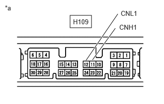
Tester Connection Condition Specified Condition H109-11 (CNH1) - H109-12 (CNL1) Always 108 to 132 Ω *a Component without harness connected
(Radio and Display Receiver Assembly) - Inspect the mobile wireless charger cradle assembly.
Standard Resistance
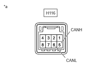
Tester Connection Condition Specified Condition H116-5 (CANH) - H116-6 (CANL) Always 200 Ω or higher *a Component without harness connected
(Mobile Wireless Charger Cradle Assembly) - Inspect the combination meter assembly.
*a Component without harness connected
(Combination Meter Assembly)Standard Resistance
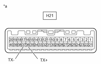
Tester Connection Condition Specified Condition H21-36 (TX+) - H21-37 (TX-) Always 108 to 132 Ω Result
Result Proceed to The results of all ECUs are as specified A The results of the radio and display receiver assembly are not as specified B The results of the mobile wireless charger cradle assembly are not as specified C The results of the combination meter assembly are not as specified D
Result:
A
REPAIR OR REPLACE HARNESS OR CONNECTOR
Result:
B
REPLACE RADIO AND DISPLAY RECEIVER ASSEMBLY. Refer to REMOVAL [10/2022 - 11/2023]
Result:
C
REPLACE MOBILE WIRELESS CHARGER CRADLE ASSEMBLY. Refer to REMOVAL [10/2022 - ]
Result:
D
REPLACE COMBINATION METER ASSEMBLY. Refer to REMOVAL [12/2019 - ]
- Remove 1 of the following ECUs.
- CHECK HARNESS AND CONNECTOR (LOCAL BUS COMMUNICATION CIRCUIT)
- Disconnect the cable from the negative (-) auxiliary battery terminal.
- Disconnect the H21 combination meter assembly connector.
- Measure the resistance according to the value(s) in the table below.
Standard Resistance
Tester Connection Condition Specified Condition H21-36 (TX+) - H21-37 (TX-) Cable disconnected from negative (-) auxiliary battery terminal 108 to 132 Ω Result
Proceed to OK NG
Result:
OK
REPLACE COMBINATION METER ASSEMBLY. Refer to REMOVAL [12/2019 - ]
Result:
NG
REPAIR OR REPLACE HARNESS OR CONNECTOR
- CHECK FOR DTC
- Check each system for DTCs.
Body Electrical > Combination Meter > Trouble Codes
Body Electrical > Navigation System > Trouble Codes
- Confirm the DTC combinations of the following table.
DTC Output Pattern DTC Output Part Name
(Display on GTS)Combination Meter Assembly
(Combination Meter)Radio and Display Receiver Assembly
(Navigation System)1 B1321-87 U11D0-87 2 B1321-87 Not output Result
Result Proceed to DTC output pattern 1 A DTC output pattern 2 B
Result:
B
See step 7
Result:
A
See step 6
- Check each system for DTCs.
- INSPECT EACH ECU (INTERNAL MALFUNCTION)
- Remove 1 of the following ECUs.
- Radio and display receiver assembly
Refer to REMOVAL [10/2022 - 11/2023]
- Combination meter assembly
Refer to REMOVAL [12/2019 - ]
- Radio and display receiver assembly
- Measure the resistance of the removed ECU.NOTE:
- Refer to the following table for the specified conditions of each ECU.
- If the specified conditions are met, repeat the inspection procedure from step (a) for another ECU.
HINT:
If the results of an ECU are not as specified, it is suspected that the ECU is the cause of the DTC.
- Inspect the radio and display receiver assembly.
Standard Resistance
Tester Connection Condition Specified Condition H109-11 (CNH1) - H109-12 (CNL1) Always 108 to 132 Ω *a Component without harness connected
(Radio and Display Receiver Assembly) - Inspect the combination meter assembly.
*a Component without harness connected
(Combination Meter Assembly)Standard Resistance
Tester Connection Condition Specified Condition H21-36 (TX+) - H21-37 (TX-) Always 108 to 132 Ω Result
Result Proceed to The results of all ECUs are as specified A The results of the radio and display receiver assembly are not as specified B The results of the combination meter assembly are not as specified C
Result:
A
REPAIR OR REPLACE HARNESS OR CONNECTOR
Result:
B
REPLACE RADIO AND DISPLAY RECEIVER ASSEMBLY. Refer to REMOVAL [10/2022 - 11/2023]
Result:
C
REPLACE COMBINATION METER ASSEMBLY. Refer to REMOVAL [12/2019 - ]
- Remove 1 of the following ECUs.
- CLEAR DTC
Result:
NEXT
See step 8
- CHECK FOR DTC
- Disconnect the cable from the negative (-) auxiliary battery terminal.
HINT:
By disconnecting the cable from the negative (-) auxiliary battery terminal, the internally stored information related to local bus communication for the combination meter assembly is reset.
- Disconnect the H109 radio and display receiver assembly connector.
- Connect the cable to the negative (-) auxiliary battery terminal.
- Turn the ignition switch to ON.
- Wait 30 seconds or more.
- Check for DTCs.
Body Electrical > Combination Meter > Trouble Codes
HINT:
By resetting the internally stored information related to local bus communication, the detection conditions of DTC B1321-87 are not met as the combination meter assembly does not detect the radio and display receiver assembly. If the combination meter assembly is operating normally, DTC B1321-87 will not be stored.
Result
Result Proceed to DTC B1321-87 is not output A DTC B1321-87 is output B
Result:
A
REPLACE RADIO AND DISPLAY RECEIVER ASSEMBLY. Refer to REMOVAL [10/2022 - 11/2023]
Result:
B
REPLACE COMBINATION METER ASSEMBLY. Refer to REMOVAL [12/2019 - ]
- Disconnect the cable from the negative (-) auxiliary battery terminal.