DTC B1500-13: Fuel Sender Circuit Open [10/2022 - ]: Procedure
- CONFIRM MODEL
Result:
B
See step 6
Result:
A
See step 2
- READ VALUE USING GTS
- Read the Data List according to the display on the GTS.
Body Electrical > Combination Meter > Data List
Tester Display Measurement Item Range Normal Condition Diagnostic Note Fuel Input Fuel level gauge output Min.: 0.00 L, Max.: 655.35 L or Unset - Fuel receiver gauge indicates F: 56.44 L
- Fuel receiver gauge indicates 3/4: 48.32 L
- Fuel receiver gauge indicates 1/2: 32.25 L
- Fuel receiver gauge indicates 1/4: 16.13 L
- Fuel receiver gauge indicates E: 6.45 L
- Body Electrical > Combination Meter > Data List
Tester Display Fuel Input Result
Result Proceed to Fuel level data can be displayed on the GTS A Fuel level data cannot be displayed on the GTS B
Result:
A
REPLACE COMBINATION METER ASSEMBLY. Refer to REMOVAL [12/2019 - ]
Result:
B
See step 3
- Read the Data List according to the display on the GTS.
- INSPECT FUEL SENDER GAUGE ASSEMBLY
- Remove the fuel sender gauge assembly.
Refer to REMOVAL [10/2022 - 11/2023] , or refer to REMOVAL [11/2023 - ]
- Inspect the fuel sender gauge assembly.
Refer to INSPECTION [12/2019 - ]
Result
Proceed to OK NG
Result:
NG
REPLACE FUEL SENDER GAUGE ASSEMBLY. Refer to REMOVAL [10/2022 - 11/2023] , or refer to REMOVAL [11/2023 - ]
Result:
OK
See step 4
- Remove the fuel sender gauge assembly.
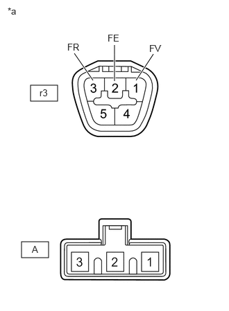
- INSPECT FUEL SUCTION TUBE WITH PUMP AND GAUGE ASSEMBLY
*a Component without harness connected
(Fuel Suction Tube with Pump and Gauge Assembly)- Measure the resistance according to the value(s) in the table below.
Standard Resistance
Tester Connection Condition Specified Condition r3-1 (FV) - A-3 Always Below 1 Ω r3-2 (FE) - A-2 Always Below 1 Ω r3-3 (FR) - A-1 Always Below 1 Ω r3-1 (FV) - r3-3 (FR)
or
A-3 - A-1Always 10 kΩ or higher r3-1 (FV) - r3-2 (FE)
or
A-3 - A-2Always 10 kΩ or higher r3-2 (FE) - r3-3 (FR)
or
A-2 - A-1Always 10 kΩ or higher Result
Proceed to OK NG
Result:
NG
REPLACE FUEL SUCTION TUBE WITH PUMP AND GAUGE ASSEMBLY. Refer to REMOVAL [10/2022 - 11/2023] , or refer to REMOVAL [11/2023 - ]
Result:
OK
See step 5
- Measure the resistance according to the value(s) in the table below.
- CHECK HARNESS AND CONNECTOR (FUEL SUCTION TUBE WITH PUMP AND GAUGE ASSEMBLY - COMBINATION METER ASSEMBLY)
- Disconnect the H21 combination meter assembly connector.
- Measure the resistance according to the value(s) in the table below.
Standard Resistance
Tester Connection Condition Specified Condition r3-1 (FV) - H21-15 (FV) Always Below 1 Ω r3-3 (FR) - H21-14 (FR) Always Below 1 Ω r3-2 (FE) - H21-33 (FE) Always Below 1 Ω r3-1 (FV) or H21-15 (FV) - Body ground Always 10 kΩ or higher r3-3 (FR) or H21-14 (FR) - Body ground Always 10 kΩ or higher Result
Proceed to OK NG
Result:
OK
REPLACE COMBINATION METER ASSEMBLY. Refer to REMOVAL [12/2019 - ]
Result:
NG
REPAIR OR REPLACE HARNESS OR CONNECTOR
- READ VALUE USING GTS
- Read the Data List according to the display on the GTS.
Body Electrical > Combination Meter > Data List
Tester Display Measurement Item Range Normal Condition Diagnostic Note Fuel Input Fuel level gauge output Min.: 0.00 L, Max.: 655.35 L or Unset - Fuel receiver gauge indicates F: 60.93 L
- Fuel receiver gauge indicates 3/4: 50.78 L
- Fuel receiver gauge indicates 1/2: 33.85 L
- Fuel receiver gauge indicates 1/4: 16.93 L
- Fuel receiver gauge indicates E: 7.74 L
- Body Electrical > Combination Meter > Data List
Tester Display Fuel Input Result
Result Proceed to Fuel level data can be displayed on the GTS A Fuel level data cannot be displayed on the GTS B
Result:
A
REPLACE COMBINATION METER ASSEMBLY. Refer to REMOVAL [12/2019 - ]
Result:
B
See step 7
- Read the Data List according to the display on the GTS.
- INSPECT FUEL SENDER GAUGE ASSEMBLY
- Remove the fuel sender gauge assembly.
Refer to REMOVAL [10/2022 - 11/2023] , or refer to REMOVAL [11/2023 - ]
- Inspect the fuel sender gauge assembly.
Refer to INSPECTION [10/2022 - ]
Result
Proceed to OK NG
Result:
NG
REPLACE FUEL SENDER GAUGE ASSEMBLY. Refer to REMOVAL [10/2022 - 11/2023] , or refer to REMOVAL [11/2023 - ]
Result:
OK
See step 8
- Remove the fuel sender gauge assembly.
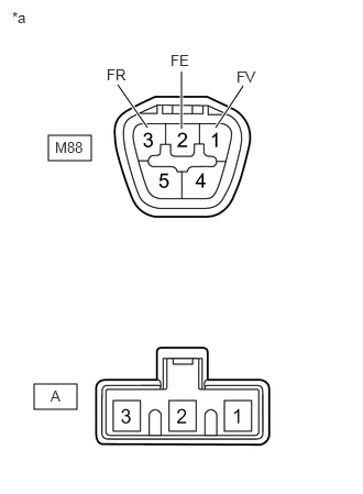
- INSPECT FUEL SUCTION TUBE WITH PUMP AND GAUGE ASSEMBLY
*a Component without harness connected
(Fuel Suction Tube with Pump and Gauge Assembly)- Measure the resistance according to the value(s) in the table below.
Standard Resistance
Tester Connection Condition Specified Condition M88-1 (FV) - A-3 Always Below 1 Ω M88-2 (FE) - A-2 Always Below 1 Ω M88-3 (FR) - A-1 Always Below 1 Ω M88-1 (FV) - M88-3 (FR)
or
A-3 - A-1Always 10 kΩ or higher M88-1 (FV) - M88-2 (FE)
or
A-3 - A-2Always 10 kΩ or higher M88-2 (FE) - M88-3 (FR)
or
A-2 - A-1Always 10 kΩ or higher Result
Proceed to OK NG
Result:
NG
REPLACE FUEL SUCTION TUBE WITH PUMP AND GAUGE ASSEMBLY. Refer to REMOVAL [10/2022 - 11/2023] , or refer to REMOVAL [11/2023 - ]
Result:
OK
See step 9
- Measure the resistance according to the value(s) in the table below.
- CHECK HARNESS AND CONNECTOR (FUEL SUCTION TUBE WITH PUMP AND GAUGE ASSEMBLY - COMBINATION METER ASSEMBLY)
- Disconnect the H21 combination meter assembly connector.
- Measure the resistance according to the value(s) in the table below.
Standard Resistance
Tester Connection Condition Specified Condition M88-1 (FV) - H21-15 (FV) Always Below 1 Ω M88-3 (FR) - H21-14 (FR) Always Below 1 Ω M88-2 (FE) - H21-33 (FE) Always Below 1 Ω M88-1 (FV) or H21-15 (FV) - Body ground Always 10 kΩ or higher M88-3 (FR) or H21-14 (FR) - Body ground Always 10 kΩ or higher Result
Proceed to OK NG
Result:
OK
REPLACE COMBINATION METER ASSEMBLY. Refer to REMOVAL [12/2019 - ]
Result:
NG
REPAIR OR REPLACE HARNESS OR CONNECTOR