Headlight Dimmer Switch Circuit [11/2023 - ]: Procedure
- READ VALUE USING GTS
- Read the Data List according to the display on the GTS.
Chassis > Steering Angle Sensor > Data List
Tester Display Measurement Item Range Normal Condition Diagnostic Note Light OFF Switch Light control switch DRL OFF position signal OFF or ON OFF: Light control switch not in DRL OFF position
ON: Light control switch in DRL OFF positionw/ DRL OFF Switch Auto Light Switch Light control switch AUTO position signal OFF or ON OFF: Light control switch not in AUTO position
ON: Light control switch in AUTO position- Head Light Switch (Tail) Light control switch tail position signal OFF or ON OFF: Light control switch in neither tail nor head position
ON: Light control switch in tail or head position- Head Light Switch (Head) Light control switch head position signal OFF or ON OFF: Light control switch not in head position
ON: Light control switch in head position- High Beam Main Switch Dimmer switch high position signal OFF or ON OFF: Dimmer switch not in high position
ON: Dimmer switch in high position- Passing Light Switch Dimmer switch high flash position (pass) signal OFF or ON OFF: Dimmer switch not in high flash position
ON: Dimmer switch in high flash position- Front Fog Light Switch Front fog light switch signal OFF or ON OFF: Front fog light switch off
ON: Front fog light switch on- Chassis > Steering Angle Sensor > Data List
Tester Display Light OFF Switch Auto Light Switch Head Light Switch (Tail) Head Light Switch (Head) High Beam Main Switch Passing Light Switch Front Fog Light Switch OK
Normal conditions listed above are displayed.
Result
Proceed to OK NG
Result:
NG
See step 5
Result:
OK
See step 2
- Read the Data List according to the display on the GTS.
- READ VALUE USING GTS
- Read the Data List according to the display on the GTS.
Body Electrical > Main Body > Data List
Tester Display Measurement Item Range Normal Condition Diagnostic Note Light Control Switch (HEAD) Light control switch head position signal OFF or ON OFF: Light control switch not in head position
ON: Light control switch in head position- Body Electrical > Main Body > Data List
Tester Display Light Control Switch (HEAD) OK
Normal conditions listed above are displayed.
Result
Proceed to OK NG
Result:
OK
PROCEED TO NEXT SUSPECTED AREA SHOWN IN PROBLEM SYMPTOMS TABLE. Refer to PROBLEM SYMPTOMS TABLE [11/2023 - ]
Result:
NG
See step 3
- Read the Data List according to the display on the GTS.
- INSPECT STEERING SENSOR
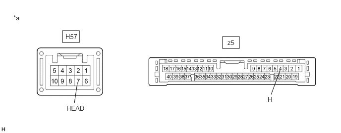
*a Component without harness connected
(Steering Sensor)- - - Remove the steering sensor.
Refer to REMOVAL [11/2023 - ]
- Measure the resistance according to the value(s) in the table below.
Standard Resistance
Tester Connection Condition Specified Condition H57-7 (HEAD) - z5-4 (H) Always Below 1 Ω Result
Proceed to OK NG
Result:
NG
REPLACE STEERING SENSOR. Refer to REMOVAL [11/2023 - ]
Result:
OK
See step 4
- Remove the steering sensor.
- CHECK HARNESS AND CONNECTOR (STEERING SENSOR - MAIN BODY ECU (MULTIPLEX NETWORK BODY ECU))
- Disconnect the H135 main body ECU (multiplex network body ECU) connector.
- Measure the resistance according to the value(s) in the table below.
Standard Resistance
Tester Connection Condition Specified Condition H57-7 (HEAD) - H135-26 (HEAD) Always Below 1 Ω H57-7 (HEAD) or H135-26 (HEAD) - Body ground Always 10 kΩ or higher Result
Proceed to OK NG
Result:
OK
REPLACE MAIN BODY ECU (MULTIPLEX NETWORK BODY ECU). Refer to REMOVAL [11/2023 - ]
Result:
NG
REPAIR OR REPLACE HARNESS OR CONNECTOR
- INSPECT TURN SIGNAL SWITCH
Refer to INSPECTION [12/2019 - ]
Result
Proceed to OK NG Result:
NG
REPLACE TURN SIGNAL SWITCH. Refer to REMOVAL [12/2019 - ]
Result:
OK
See step 6
- INSPECT STEERING WHEEL SWITCH HOUSING
Refer to INSPECTION [12/2019 - ]
Result
Proceed to OK NG Result:
OK
REPLACE STEERING SENSOR. Refer to REMOVAL [11/2023 - ]
Result:
NG
REPLACE STEERING WHEEL SWITCH HOUSING. Refer to REMOVAL [11/2023 - ]