Back-up Light Circuit [11/2023 - ]: Procedure
- READ VALUE USING GTS
- Turn the ignition switch to ON.
- Move the shift lever to R.
- Read the Data List according to the display on the GTS.
Body Electrical > Power Distribution Box > Data List
Tester Display Measurement Item Normal Condition Reference Value Diagnostic Note Back-up Light Fuse Shut Off Status Back-up light fuse shut off status OFF or ON OFF: Fuse has no shut off history
ON: Fuse has shut off history- Body Electrical > Power Distribution Box > Data List
Tester Display Back-up Light Fuse Shut Off Status OK
The Data List value displays "OFF".
Result
Proceed to OK NG
Result:
NG
See step 8
Result:
OK
See step 2
- READ VALUE USING GTS
- Read the Data List according to the display on the GTS.
Body Electrical > Power Distribution Box > Data List
Tester Display Measurement Item Normal Condition Reference Value Diagnostic Note Back-up Light Input Signal Back-up light input OFF or ON OFF: Shift lever in any position other than R
ON: Shift lever in R- Body Electrical > Power Distribution Box > Data List
Tester Display Back-up Light Input Signal OK
Display changes according to shift lever operation.
Result
Proceed to OK NG
Result:
NG
See step 6
Result:
OK
See step 3
- Read the Data List according to the display on the GTS.
- CHECK HARNESS AND CONNECTOR (POWER SOURCE - POWER DISTRIBUTION BOX ASSEMBLY)
- Disconnect the 8J power distribution box assembly connector.
- Measure the voltage according to the value(s) in the table below.
Standard Voltage
Tester Connection Condition Specified Condition 8J-1 - Body ground Ignition switch off 11 to 14 V Result
Proceed to OK NG
Result:
NG
REPAIR OR REPLACE HARNESS OR CONNECTOR
Result:
OK
See step 4
- CHECK HARNESS AND CONNECTOR (REAR LIGHT ASSEMBLY - POWER DISTRIBUTION BOX ASSEMBLY)
- Disconnect the W7 rear light assembly RH connector.
- Disconnect the W8 rear light assembly LH connector.
- Disconnect the 8G power distribution box assembly connector.
- Measure the resistance according to the value(s) in the table below.
Standard Resistance
Tester Connection Condition Specified Condition W7-1 (B) - 8G-38 Always Below 1 Ω W8-1 (B) - 8G-38 Always Below 1 Ω Result
Proceed to OK NG
Result:
NG
REPAIR OR REPLACE HARNESS OR CONNECTOR
Result:
OK
See step 5
- CHECK HARNESS AND CONNECTOR (REAR LIGHT ASSEMBLY - BODY GROUND)
- Measure the resistance according to the value(s) in the table below.
Standard Resistance
Tester Connection Condition Specified Condition W7-3 (E) - Body ground Always Below 1 Ω W8-3 (E) - Body ground Always Below 1 Ω Result
Proceed to OK NG
Result:
OK
REPLACE POWER DISTRIBUTION BOX ASSEMBLY. Refer to REMOVAL [11/2023 - ]
Result:
NG
REPAIR OR REPLACE HARNESS OR CONNECTOR
- Measure the resistance according to the value(s) in the table below.
- CHECK HARNESS AND CONNECTOR (HYBRID VEHICLE CONTROL ECU - POWER DISTRIBUTION BOX ASSEMBLY)
- Disconnect the H67 hybrid vehicle control ECU connector.
- Disconnect the 8B power distribution box assembly connector.
- Measure the resistance according to the value(s) in the table below.
Standard Resistance
Tester Connection Condition Specified Condition H67-49 (BL) - 8B-29 Always Below 1 Ω H67-49 (BL) or 8B-29 - Body ground Always 10 kΩ or higher Result
Proceed to OK NG
Result:
NG
REPAIR OR REPLACE HARNESS OR CONNECTOR
Result:
OK
See step 7
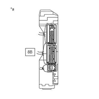
- CHECK HYBRID VEHICLE CONTROL ECU (OUTPUT VOLTAGE)
*a Component with harness connected
(Power Distribution Box Assembly)- Connect the H67 hybrid vehicle control ECU connector.
- Connect the 8B power distribution box assembly connectors.
- Measure the voltage according to the value(s) in the table below.
Standard Voltage
Tester Connection Condition Specified Condition 8B-29 - Body ground Ignition switch off, reverse (R) not selected Below 1 V 8B-29 - Body ground Ignition switch ON, reverse (R) selected 11 to 14 V Result
Proceed to OK NG
Result:
OK
REPLACE POWER DISTRIBUTION BOX ASSEMBLY. Refer to REMOVAL [11/2023 - ]
Result:
NG
REPLACE HYBRID VEHICLE CONTROL ECU. Refer to REMOVAL [11/2023 - ]
- CHECK REAR LIGHT ASSEMBLY RH
- Disconnect the W7 rear light assembly RH connector.
- Turn the ignition switch to ON.
- Move the shift lever to R.
- Read the Data List according to the display on the GTS.
Body Electrical > Power Distribution Box > Data List
Tester Display Measurement Item Normal Condition Reference Value Diagnostic Note Back-up Light Fuse Shut Off Status Back-up light fuse shut off status OFF or ON OFF: Fuse has no shut off history
ON: Fuse has shut off history- Body Electrical > Power Distribution Box > Data List
Tester Display Back-up Light Fuse Shut Off Status OK
The Data List value displays "OFF".
Result
Proceed to OK NG
Result:
OK
REPLACE REAR LIGHT ASSEMBLY RH. Refer to REMOVAL [12/2019 - ]
Result:
NG
See step 9
- CHECK REAR LIGHT ASSEMBLY LH
- Disconnect the W8 rear light assembly LH connector.
- Turn the ignition switch to ON.
- Move the shift lever to R.
- Read the Data List according to the display on the GTS.
Body Electrical > Power Distribution Box > Data List
Tester Display Measurement Item Normal Condition Reference Value Diagnostic Note Back-up Light Fuse Shut Off Status Back-up light fuse shut off status OFF or ON OFF: Fuse has no shut off history
ON: Fuse has shut off history- Body Electrical > Power Distribution Box > Data List
Tester Display Back-up Light Fuse Shut Off Status OK
The Data List value displays "OFF".
Result
Proceed to OK NG
Result:
OK
REPLACE REAR LIGHT ASSEMBLY LH. Refer to REMOVAL [12/2019 - ]
Result:
NG
See step 10
- CHECK HARNESS AND CONNECTOR (REAR LIGHT ASSEMBLY - POWER DISTRIBUTION BOX ASSEMBLY)
- Disconnect the 8G power distribution box assembly connector.
- Measure the resistance according to the value(s) in the table below.
Standard Resistance
Tester Connection Condition Specified Condition W7-1 (B), W8-1 (B) or 8G-38 - Body ground Always 10 kΩ or higher Result
Proceed to OK NG
Result:
OK
REPLACE POWER DISTRIBUTION BOX ASSEMBLY. Refer to REMOVAL [11/2023 - ]
Result:
NG
REPAIR OR REPLACE HARNESS OR CONNECTOR