DTC B242F-14: ECUB Circuit Short to Ground or Open [11/2023 - ]: Procedure
- CLEAR DTC
- Clear the DTCs.
Body Electrical > Headlight Control > Clear DTCs
Body Electrical > Headlight Control (Sub) > Clear DTCs
Result
Proceed to NEXT
Result:
NEXT
See step 2
- Clear the DTCs.
- CHECK FOR DTC
- Turn the ignition switch to ON.
- Wait 10 seconds or more.
- Check for DTCs.
Body Electrical > Headlight Control > Trouble Codes
Body Electrical > Headlight Control (Sub) > Trouble Codes
OK
DTC B242F-14 is not output.
Result
Result Proceed to OK A NG (DTC output from headlight ECU sub-assembly LH) B NG (DTC output from headlight ECU sub-assembly RH) C
Result:
A
USE SIMULATION METHOD TO CHECK. Refer to HOW TO PROCEED WITH TROUBLESHOOTING [12/2019 - ]
Result:
C
See step 10
Result:
B
See step 3
- CHECK HARNESS AND CONNECTOR (HEADLIGHT ECU SUB-ASSEMBLY LH - AUXILIARY BATTERY)
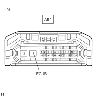
*a Front view of wire harness connector
(to Headlight ECU Sub-assembly LH)- Disconnect the headlight ECU sub-assembly LH connector.
- Measure the voltage according to the value(s) in the table below.
Standard Voltage
Tester Connection Switch Condition Specified Condition A87-13 (ECUB) - Body ground Ignition switch ON 11 to 14 V Result
Proceed to OK NG
Result:
NG
See step 5
Result:
OK
See step 4
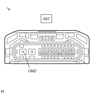
- CHECK HARNESS AND CONNECTOR (HEADLIGHT ECU SUB-ASSEMBLY LH - BODY GROUND)
- Disconnect the headlight ECU sub-assembly LH connector.
- Measure the resistance according to the value(s) in the table below.
Standard Resistance
Tester Connection Condition Specified Condition A87-12 (GND) - Body ground Always Below 1 Ω *a Front view of wire harness connector
(to Headlight ECU Sub-assembly LH)Result
Proceed to OK NG
Result:
OK
REPLACE HEADLIGHT ECU SUB-ASSEMBLY LH. Refer to REMOVAL [11/2023 - ]
Result:
NG
REPAIR OR REPLACE HARNESS OR CONNECTOR
- INSPECT H-LP LH RELAY
Refer to ON-VEHICLE INSPECTION [12/2019 - ]
Result
Proceed to OK NG Result:
NG
REPLACE H-LP LH RELAY
Result:
OK
See step 6
- CHECK HARNESS AND CONNECTOR (H-LP LH RELAY - HEADLIGHT ECU SUB-ASSEMBLY LH)
- Remove the H-LP LH relay.
- Disconnect the A87 headlight ECU sub-assembly LH connector.
- Measure the resistance according to the value(s) in the table below.
Standard Resistance
Tester Connection Condition Specified Condition 3 (H-LP LH relay) - A87-13 (ECUB) Always Below 1 Ω 3 (H-LP LH relay) or A87-13 (ECUB) - Body ground Always 10 kΩ or higher Result
Proceed to OK NG
Result:
NG
REPAIR OR REPLACE HARNESS OR CONNECTOR
Result:
OK
See step 7
- CHECK HARNESS AND CONNECTOR (H-LP LH RELAY - AUXILIARY BATTERY)
- Remove the H-LP LH relay.
- Measure the voltage according to the value(s) in the table below.
Standard Voltage
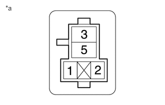
Tester Connection Switch Condition Specified Condition 2 (H-LP LH relay) - Body ground Ignition switch off 11 to 14 V 5 (H-LP LH relay) - Body ground Ignition switch off 11 to 14 V *a Front view of wire harness connector
(to H-LP LH Relay)Result
Proceed to OK NG
Result:
NG
REPAIR OR REPLACE HARNESS OR CONNECTOR
Result:
OK
See step 8
- CHECK HARNESS AND CONNECTOR (H-LP LH RELAY - POWER DISTRIBUTION BOX ASSEMBLY)
- Remove the H-LP LH relay.
- Disconnect the 8E power distribution box assembly connector.
- Measure the resistance according to the value(s) in the table below.
Standard Resistance
Tester Connection Condition Specified Condition 1 (H-LP LH relay) - 8E-6 Always Below 1 Ω 1 (H-LP LH relay) or 8E-6 - Body ground Always 10 kΩ or higher Result
Proceed to OK NG
Result:
NG
REPAIR OR REPLACE HARNESS OR CONNECTOR
Result:
OK
See step 9
- INSPECT POWER DISTRIBUTION BOX ASSEMBLY
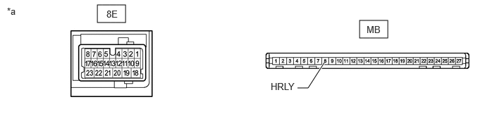
*a Component without harness connected
(Power Distribution Box Assembly)- - - Remove the power distribution box assembly.
Refer to REMOVAL [11/2023 - ]
- Remove the main body ECU (multiplex network body ECU) from the power distribution box assembly.
- Measure the resistance according to the value(s) in the table below.
Standard Resistance
Tester Connection Condition Specified Condition 8E-6 - MB-8 (HRLY) Always Below 1 Ω Result
Proceed to OK NG
Result:
OK
REPLACE MAIN BODY ECU (MULTIPLEX NETWORK BODY ECU). Refer to REMOVAL [11/2023 - ]
Result:
NG
REPLACE POWER DISTRIBUTION BOX ASSEMBLY. Refer to REMOVAL [11/2023 - ]
- Remove the power distribution box assembly.
- CHECK HARNESS AND CONNECTOR (HEADLIGHT ECU SUB-ASSEMBLY RH - AUXILIARY BATTERY)
*a Front view of wire harness connector
(to Headlight ECU Sub-assembly RH)- Disconnect the headlight ECU sub-assembly RH connector.
- Measure the voltage according to the value(s) in the table below.
Standard Voltage
Tester Connection Switch Condition Specified Condition A16-13 (ECUB) - Body ground Ignition switch ON 11 to 14 V Result
Proceed to OK NG
Result:
NG
See step 12
Result:
OK
See step 11
- CHECK HARNESS AND CONNECTOR (HEADLIGHT ECU SUB-ASSEMBLY RH - BODY GROUND)
- Disconnect the headlight ECU sub-assembly RH connector.
- Measure the resistance according to the value(s) in the table below.
Standard Resistance
Tester Connection Condition Specified Condition A16-12 (GND) - Body ground Always Below 1 Ω *a Front view of wire harness connector
(to Headlight ECU Sub-assembly RH)Result
Proceed to OK NG
Result:
OK
REPLACE HEADLIGHT ECU SUB-ASSEMBLY RH. Refer to REMOVAL [11/2023 - ]
Result:
NG
REPAIR OR REPLACE HARNESS OR CONNECTOR
- INSPECT H-LP RH RELAY
Refer to ON-VEHICLE INSPECTION [12/2019 - ]
Result
Proceed to OK NG Result:
NG
REPLACE H-LP RH RELAY
Result:
OK
See step 13
- CHECK HARNESS AND CONNECTOR (H-LP RH RELAY - HEADLIGHT ECU SUB-ASSEMBLY RH)
- Remove the H-LP RH relay.
- Disconnect the A16 headlight ECU sub-assembly RH connector.
- Measure the resistance according to the value(s) in the table below.
Standard Resistance
Tester Connection Condition Specified Condition 3 (H-LP RH relay) - A16-13 (ECUB) Always Below 1 Ω 3 (H-LP RH relay) or A16-13 (ECUB) - Body ground Always 10 kΩ or higher Result
Proceed to OK NG
Result:
NG
REPAIR OR REPLACE HARNESS OR CONNECTOR
Result:
OK
See step 14
- CHECK HARNESS AND CONNECTOR (H-LP RH RELAY - AUXILIARY BATTERY)
- Remove the H-LP RH relay.
- Measure the voltage according to the value(s) in the table below.
Standard Voltage
Tester Connection Switch Condition Specified Condition 2 (H-LP RH relay) - Body ground Ignition switch off 11 to 14 V 5 (H-LP RH relay) - Body ground Ignition switch off 11 to 14 V *a Front view of wire harness connector
(to H-LP RH Relay)Result
Proceed to OK NG
Result:
NG
REPAIR OR REPLACE HARNESS OR CONNECTOR
Result:
OK
See step 15
- CHECK HARNESS AND CONNECTOR (H-LP RH RELAY - POWER DISTRIBUTION BOX ASSEMBLY)
- Remove the H-LP RH relay.
- Disconnect the 8E power distribution box assembly connector.
- Measure the resistance according to the value(s) in the table below.
Standard Resistance
Tester Connection Condition Specified Condition 1 (H-LP RH relay) - 8E-10 Always Below 1 Ω 1 (H-LP RH relay) or 8E-10 - Body ground Always 10 kΩ or higher Result
Proceed to OK NG
Result:
NG
REPAIR OR REPLACE HARNESS OR CONNECTOR
Result:
OK
See step 16
- INSPECT POWER DISTRIBUTION BOX ASSEMBLY
*a Component without harness connected
(Power Distribution Box Assembly)- - - Remove the power distribution box assembly.
Refer to REMOVAL [11/2023 - ]
- Remove the main body ECU (multiplex network body ECU) from the power distribution box assembly.
- Measure the resistance according to the value(s) in the table below.
Standard Resistance
Tester Connection Condition Specified Condition 8E-10 - MB-9 (HRY2) Always Below 1 Ω Result
Proceed to OK NG
Result:
OK
REPLACE MAIN BODY ECU (MULTIPLEX NETWORK BODY ECU). Refer to REMOVAL [11/2023 - ]
Result:
NG
REPLACE POWER DISTRIBUTION BOX ASSEMBLY. Refer to REMOVAL [11/2023 - ]
- Remove the power distribution box assembly.