DCM Data Signal Circuit between Navigation ECU and DCM [12/2019 - 10/2022]: Procedure
- CHECK MODEL
- Choose the model to be inspected.
Result
Result Proceed to For 8 Inch Display A For 12.3 Inch Display B
Result:
B
See step 4
Result:
A
See step 2
- Choose the model to be inspected.
- CHECK HARNESS AND CONNECTOR (RADIO AND DISPLAY RECEIVER ASSEMBLY - DCM (TELEMATICS TRANSCEIVER))
- Disconnect the H11 DCM (telematics transceiver) connector.
- Disconnect the H3 radio and display receiver assembly connector.
- Measure the resistance according to the value(s) in the table below.
Standard Resistance
Tester Connection Condition Specified Condition H11-31 (USBG) - H3-11 (USBG) Always Below 1 Ω H11-17 (VOT+) - H3-13 (VOR+) Always Below 1 Ω H11-15 (USBV) - H3-10 (USBV) Always Below 1 Ω H11-33 (VOT-) - H3-14 (VOR-) Always Below 1 Ω H11-34 (VOR-) - H3-16 (VOT-) Always Below 1 Ω H11-18 (VOR+) - H3-15 (VOT+) Always Below 1 Ω H11-31 (USBG) or H3-11 (USBG) - Body ground Always 10 kΩ or higher H11-17 (VOT+) or H3-13 (VOR+) - Body ground Always 10 kΩ or higher H11-15 (USBV) or H3-10 (USBV) - Body ground Always 10 kΩ or higher H11-33 (VOT-) or H3-14 (VOR-) - Body ground Always 10 kΩ or higher H11-34 (VOR-) or H3-16 (VOT-) - Body ground Always 10 kΩ or higher H11-18 (VOR+) or H3-15 (VOT+) - Body ground Always 10 kΩ or higher Result
Proceed to OK NG
Result:
NG
REPAIR OR REPLACE HARNESS OR CONNECTOR
Result:
OK
See step 3
- CHECK HARNESS AND CONNECTOR (NAVIGATION ECU - DCM (TELEMATICS TRANSCEIVER))
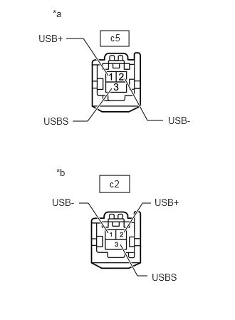
- Disconnect the c5 navigation ECU connector.
*a Front view of wire harness connector
(to Navigation ECU)*b Front view of wire harness connector
(to DCM (Telematics Transceiver))*A w/o Stereo Component Amplifier *B w/ Stereo Component Amplifier - Disconnect the c2 DCM (telematics transceiver) connector.
- Measure the resistance according to the value(s) in the table below.
Tester Connection Condition Specified Condition c5-1 (USB+) - c2-2 (USB+) Always Below 1 Ω c5-2 (USB-) - c2-1 (USB-) Always Below 1 Ω c5-3 (USBS) - c2-3 (USBS) Always Below 1 Ω c5-1 (USB+) or c2-2 (USB+) - Body ground Always 10 kΩ or higher c5-2 (USB-) or c2-1 (USB-) - Body ground Always 10 kΩ or higher c5-3 (USBS) or c2-3 (USBS) - Body ground Always 10 kΩ or higher Result
Proceed to OK NG
Result:
OK
PROCEED TO NEXT SUSPECTED AREA SHOWN IN PROBLEM SYMPTOMS TABLE. Refer to PROBLEM SYMPTOMS TABLE [12/2019 - 10/2022]
Result:
NG
REPAIR OR REPLACE HARNESS OR CONNECTOR
- Disconnect the c5 navigation ECU connector.
- CHECK HARNESS AND CONNECTOR (RADIO RECEIVER ASSEMBLY - DCM (TELEMATICS TRANSCEIVER))
- Disconnect the H11 DCM (telematics transceiver) connector.
- Disconnect the H6 radio and display receiver assembly connector.
- Measure the resistance according to the value(s) in the table below.
Standard Resistance
Tester Connection Condition Specified Condition H11-31 (USBG) - H6-11 (USBG) Always Below 1 Ω H11-17 (VOT+) - H6-13 (VOR+) Always Below 1 Ω H11-15 (USBV) - H6-10 (USBV) Always Below 1 Ω H11-33 (VOT-) - H6-14 (VOR-) Always Below 1 Ω H11-34 (VOR-) - H6-16 (VOT-) Always Below 1 Ω H11-18 (VOR+) - H6-15 (VOT+) Always Below 1 Ω H11-31 (USBG) or H6-11 (USBG) - Body ground Always 10 kΩ or higher H11-17 (VOT+) or H6-13 (VOR+) - Body ground Always 10 kΩ or higher H11-15 (USBV) or H6-10 (USBV) - Body ground Always 10 kΩ or higher H11-33 (VOT-) or H6-14 (VOR-) - Body ground Always 10 kΩ or higher H11-34 (VOR-) or H6-16 (VOT-) - Body ground Always 10 kΩ or higher H11-18 (VOR+) or H6-15 (VOT+) - Body ground Always 10 kΩ or higher Result
Proceed to OK NG
Result:
NG
REPAIR OR REPLACE HARNESS OR CONNECTOR
Result:
OK
See step 5
- CHECK HARNESS AND CONNECTOR (NAVIGATION ECU - DCM (TELEMATICS TRANSCEIVER))
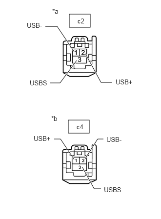
- Disconnect the c2 DCM (telematics transceiver) connector.
*a Front view of wire harness connector
(to DCM (Telematics Transceiver))*b Front view of wire harness connector
(to Navigation ECU) - Disconnect the c4 navigation ECU connector.
- Measure the resistance according to the value(s) in the table below.
Standard Resistance
Tester Connection Condition Specified Condition c2-1 (USB-) - c4-2 (USB-) Always Below 1 Ω c2-2 (USB+) - c4-1 (USB+) Always Below 1 Ω c2-3 (USBS) - c4-3 (USBS) Always Below 1 Ω c2-1 (USB-) or c4-2 (USB-) - Body ground Always 10 kΩ or higher c2-2 (USB+) or c4-1 (USB+) - Body ground Always 10 kΩ or higher c2-3 (USBS) or c4-3 (USBS) - Body ground Always 10 kΩ or higher Result
Proceed to OK NG
Result:
OK
PROCEED TO NEXT SUSPECTED AREA SHOWN IN PROBLEM SYMPTOMS TABLE. Refer to PROBLEM SYMPTOMS TABLE [12/2019 - 10/2022]
Result:
NG
REPAIR OR REPLACE HARNESS OR CONNECTOR
- Disconnect the c2 DCM (telematics transceiver) connector.