Terminals Of Ecu [12/2019 - 10/2022]
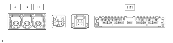
- CHECK DCM (TELEMATICS TRANSCEIVER)
Terminal No. (Symbol) Terminal Description Condition Specified Condition H11-1 (+B) - H11-20 (E) Power source (+B) Ignition switch off*1
Always*211 to 14 V*3
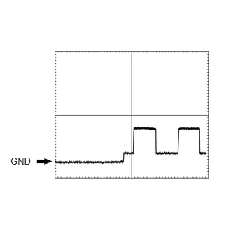
10.5 to 16 V*4H11-3 (SIG-) - H11-20 (E) Ground Always Below 1 V H11-4 (IND1) - H11-20 (E) Manual (SOS) switch red indicator illumination signal For 2 seconds after ignition switch turned to ON 1 to 8.5 V Ignition switch off Below 1 V H11-5 (MCVD) - H11-20 (E) Telephone microphone assembly power supply Ignition switch ON 4 to 6 V Ignition switch off Below 1 V H11-6 (MCI+) - H11-20 (E) Receive microphone voice signal Voice being input to telephone microphone assembly A waveform synchronized with microphone voice signal is input H11-7 (MCI-) - H11-20 (E) Receive microphone voice signal Always Below 1 V H11-13 (GSW) - H11-20 (E) Collision detection signal Ignition switch ON Pulse generation (Refer to waveform1) H11-19 (IG2) - H11-20 (E) Power source (IG) Ignition switch ON 11 to 14 V*3
10.5 to 16 V*4Ignition switch off Below 1 V H11-20 (E) - Body ground Ground Always Below 1 Ω H11-21 (SIG1) - H11-3 (SIG-) Manual (SOS) switch button condition signal Manual (SOS) switch not pressed 1.3 to 1.9 V Manual (SOS) switch pressed 0.5 to 0.8 V H11-22 (IND2) - H11-20 (E) Manual (SOS) switch green indicator illumination signal For 2 seconds after ignition switch turned to ON 1 to 8.5 V Ignition switch off Below 1 V H11-23 (SGND) - H11-20 (E) Shield ground Always Below 1 Ω H11-25 (CANP) CAN communication signal - - H11-26 (CANN) CAN communication signal - - *1: for HV Model
*2: for Gasoline Model
*3: w/o Stop and Start System
*4: w/ Stop and Start System
- CHECK RADIO AND DISPLAY RECEIVER ASSEMBLY (for 8 Inch Display)
w/o Navigation System: Refer to TERMINALS OF ECU [12/2019 - 10/2022]
w/ Navigation System: Refer to TERMINALS OF ECU [12/2019 - 10/2022]
- CHECK RADIO RECEIVER ASSEMBLY (for 12.3 Inch Display)
Refer to TERMINALS OF ECU [12/2019 - 10/2022]