Terminals Of Ecu [12/2019 - 10/2022]
- REAR TELEVISION CAMERA ASSEMBLY
 Courtesy of © TOYOTA, LICENSE AGREEMENT TMS1002
- Disconnect the W15 rear television camera assembly connector.
- Measure the voltage on the wire harness side connector according to the value(s) in the table below.
Terminal No. (Symbol) Terminal Description Switch Condition Specified Condition W15-6 (CB+) - Body ground Power source Ignition switch ACC 5.5 to 7.05 V If the result is not as specified, there may be a malfunction on the wire harness side.
- Reconnect the W15 rear television camera assembly connector.
- Measure the resistance and check for pulses at each terminal of the connector.
Terminal No. (Symbol) Terminal Description Condition Specified Condition W15-3 (CV+) - W15-2 (CV-) Video signal Ignition switch ON
Shift position in R
Camera lens not covered, displaying imagePulse generation
(Refer to waveform 1)Ignition switch ON
Shift position in R
Camera lens covered, blacking out screenPulse generation
(Refer to waveform 2)W15-5 (CGND) - Body ground Camera ground Always Below 1 Ω If the result is not as specified, the rear television camera assembly may be malfunctioning.
- Reference (Oscilloscope waveform):
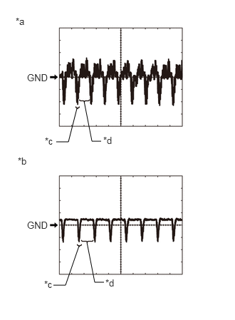
*a Waveform 1 (camera lens is not covered, displaying image) *b Waveform 2 (camera lens is covered, blacking out screen) *c Synchronization Signal *d Video Waveform - Waveform 1 (camera lens is not covered, displaying an image)
Item Content Measurement terminal W15-3 (CV+) - W15-2 (CV-) Measurement setting 200 mV/DIV., 50 μs./DIV. Condition Ignition switch ON, shift position in R, camera lens not covered, displaying image HINT:
- The video waveform changes according to the image sent by the rear television camera assembly.
- The video waveform is constantly output when the ignition switch is ACC.
- Waveform 2 (camera lens is covered, blacking out the screen)
Item Content Measurement terminal W15-3 (CV+) - W15-2 (CV-) Measurement setting 200 mV/DIV., 50 μs./DIV. Condition Ignition switch ON, shift position in R, camera lens covered, blacking out screen HINT:
- The video waveform changes according to the image sent by the rear television camera assembly.
- The video waveform is constantly output when the ignition switch is ACC.
- Waveform 1 (camera lens is not covered, displaying an image)
- RADIO AND DISPLAY RECEIVER ASSEMBLY
w/ Navigation System:
Refer to TERMINALS OF ECU [12/2019 - 10/2022]
w/ Audio and Visual System:
Refer to TERMINALS OF ECU [12/2019 - 10/2022]