DTC U0232: Lost Communication with Blind Spot Monitor Slave Module [12/2019 - 11/2023]: Procedure
- CONFIRM MODEL
- Choose the model to be inspected.
Result
Result Proceed to w/ Parking Support Alert System A w/o Parking Support Alert System B
Result:
B
See step 3
Result:
A
See step 2
- Choose the model to be inspected.
- CHECK DTC OUTPUT (PARKING SUPPORT BRAKE SYSTEM)
- Using the GTS, check for DTCs according to the prompts on the screen.
Refer to DTC CHECK / CLEAR [12/2019 - 11/2023]
Body Electrical > Clearance Warning > Trouble Codes
Standard
The clearance warning ECU assembly does not output DTCs U1177-87 and U1178-87 simultaneously.
Result
Proceed to OK NG
Result:
NG
GO TO PARKING SUPPORT BRAKE SYSTEM (DTC U1177-87). Refer to DTC U1177-87: Lost Communication with Side Obstacle Detection Control Module "A" (ch2) Missing Message; DTC U1178-87: Lost Communication with Side Obstacle Detection Control Module "B" (ch2) Missing Message [12/2019 - 11/2023]
Result:
OK
See step 3
- Using the GTS, check for DTCs according to the prompts on the screen.
- CHECK CAN BUS MAIN WIRE
- Turn the ignition switch off.
- Disconnect the cable from the negative (-) auxiliary battery terminal.
- Measure the resistance according to the value(s) in the table below.
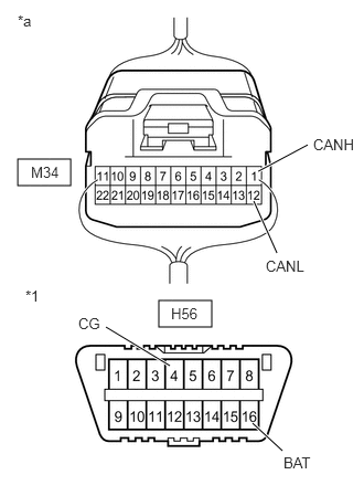
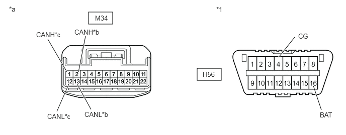
*1 DLC3 *a Component with harness connected
(No. 22 CAN Junction Connector)Standard Resistance
Tester Connection Condition Specified Condition Result M34-1 (CANH) - M34-12 (CANL) Cable disconnected from negative (-) auxiliary battery terminal 54 to 69 Ω Below 54 Ω: Short circuit between bus lines 70 Ω or more: Open circuit in main bus lines M34-1 (CANH) - H56-4 (CG) Cable disconnected from negative (-) auxiliary battery terminal 200 Ω or higher Below 200 Ω: CANH short to ground M34-12 (CANL) - H56-4 (CG) Cable disconnected from negative (-) auxiliary battery terminal 200 Ω or higher Below 200 Ω: CANL short to ground M34-1 (CANH) - H56-16 (BAT) Cable disconnected from negative (-) auxiliary battery terminal 6 kΩ or higher Below 6 kΩ: CANH +B short M34-12 (CANL) - H56-16 (BAT) Cable disconnected from negative (-) auxiliary battery terminal 6 kΩ or higher Below 6 kΩ: CANL +B short Result
Result Proceed to OK A Open circuit in CAN main bus lines B Short circuit between bus lines C - Short to ground
- +B short
D
Result:
B
See step 9
Result:
C
See step 12
Result:
D
See step 15
Result:
A
See step 4
- CHECK HARNESS AND CONNECTOR (BLIND SPOT MONITOR SENSOR RH (SLAVE) - BODY GROUND)
- Disconnect the M2 blind spot monitor sensor RH (slave) connector.
- Measure the resistance according to the value(s) in the table below.
Standard Resistance
Tester Connection Condition Specified Condition M2-10 (BRGD) - Body ground Always Below 1 Ω Result
Proceed to OK NG
Result:
NG
REPAIR OR REPLACE HARNESS OR CONNECTOR
Result:
OK
See step 5
- CHECK HARNESS AND CONNECTOR (BLIND SPOT MONITOR SENSOR RH (SLAVE) POWER SOURCE)
- Disconnect the M2 blind spot monitor sensor RH (slave) connector.
- Measure the voltage according to the value(s) in the table below.
Standard Voltage
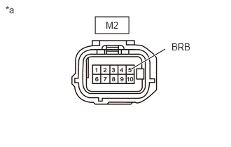
Tester Connection Switch Condition Specified Condition M2-5 (BRB) - Body ground Ignition switch ON 11 to 14 V*1
10.5 to 16 V*2M2-5 (BRB) - Body ground Ignition switch off Below 1 V *a Front view of wire harness connector
(to Blind Spot Monitor Sensor RH (Slave))- *1: w/o Stop and Start System
- *2: w/ Stop and Start System
Result
Result Proceed to OK A NG (w/o Stop and Start System) B NG (w/ Stop and Start System) C
Result:
B
REPAIR OR REPLACE HARNESS OR CONNECTOR
Result:
C
GO TO STOP AND START SYSTEM. Refer to HOW TO PROCEED WITH TROUBLESHOOTING [12/2019 - 10/2022] , or refer to HOW TO PROCEED WITH TROUBLESHOOTING [10/2022 - ]
Result:
A
See step 6
- CHECK DTC
- Reconnect the cable to the negative (-) auxiliary battery terminal.
- Turn the ignition switch off.
- Turn the ignition switch to ON.
- Check for DTCs.
Refer to DTC CHECK / CLEAR [12/2019 - 11/2023]
Body Electrical > Blind Spot Monitor Master > Trouble Codes
OK
No DTCs are output.
Result
Proceed to OK NG
Result:
OK
USE SIMULATION METHOD TO CHECK. Refer to HOW TO PROCEED WITH TROUBLESHOOTING [12/2019 - ]
Result:
NG
See step 7
- REPLACE BLIND SPOT MONITOR SENSOR RH (SLAVE)
- Refer to REMOVAL [12/2019 - 10/2022]
, or refer to REMOVAL [10/2022 - 11/2023]
Result
Proceed to NEXT
Result:
NEXT
See step 8
- Refer to REMOVAL [12/2019 - 10/2022]
, or refer to REMOVAL [10/2022 - 11/2023]
- RECHECK DTC
- Clear the DTCs.
Body Electrical > Blind Spot Monitor Master > Clear DTCs
- Recheck for DTCs and check if the same DTC is output again.
Body Electrical > Blind Spot Monitor Master > Trouble Codes
OK
No DTCs are output.
Result
Proceed to OK NG
Result:
OK
END
Result:
NG
REPLACE BLIND SPOT MONITOR SENSOR LH (MASTER). Refer to REMOVAL [12/2019 - 10/2022] , or refer to REMOVAL [10/2022 - 11/2023]
- Clear the DTCs.
- CHECK FOR OPEN IN CAN BUS MAIN WIRE (NO. 22 CAN JUNCTION CONNECTOR)
- Disconnect the No. 22 CAN junction connector.
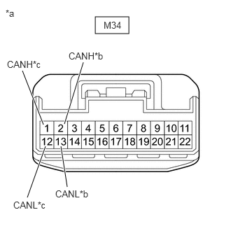
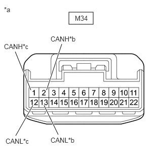
*a Front view of wire harness connector
(to No. 22 CAN Junction Connector)*b to Blind Spot Monitor Sensor LH (Master) CAN Main Wire *c to Blind Spot Monitor Sensor RH (Slave) CAN Main Wire - Measure the resistance according to the value(s) in the table below.
Standard Resistance
Tester Connection Condition Specified Condition M34-1 (CANH) - M34-12 (CANL) Cable disconnected from negative (-) auxiliary battery terminal 108 to 132 Ω M34-2 (CANH) - M34-13 (CANL) Cable disconnected from negative (-) auxiliary battery terminal 108 to 132 Ω Result
Result Proceed to OK A NG (to blind spot monitor sensor LH (master) CAN main wire) B NG (to blind spot monitor sensor RH (slave) CAN main wire) C
Result:
A
REPLACE NO. 22 CAN JUNCTION CONNECTOR
Result:
C
See step 11
Result:
B
See step 10
- Disconnect the No. 22 CAN junction connector.
- CHECK FOR OPEN IN CAN BUS MAIN WIRE (BLIND SPOT MONITOR SENSOR LH (MASTER))
- Reconnect the M34 No. 22 CAN junction connector.
- Disconnect the M43 blind spot monitor sensor LH (master) connector.
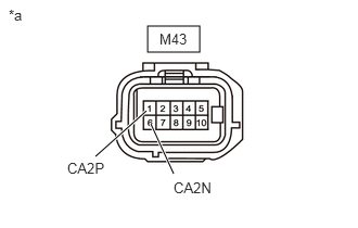
*a Front view of wire harness connector
(to Blind Spot Monitor Sensor LH (Master)) - Measure the resistance according to the value(s) in the table below.
Standard Resistance
Tester Connection Condition Specified Condition M43-1 (CA2P) - M43-6 (CA2N) Cable disconnected from negative (-) auxiliary battery terminal 108 to 132 Ω Result
Proceed to OK NG
Result:
OK
REPLACE BLIND SPOT MONITOR SENSOR LH (MASTER). Refer to REMOVAL [12/2019 - 10/2022] , or refer to REMOVAL [10/2022 - 11/2023]
Result:
NG
REPAIR OR REPLACE CAN MAIN WIRE OR CONNECTOR (BLIND SPOT MONITOR SENSOR LH (MASTER) - NO. 22 CAN JUNCTION CONNECTOR)
- CHECK FOR OPEN IN CAN BUS MAIN WIRE (BLIND SPOT MONITOR SENSOR RH (SLAVE))
- Reconnect the M34 No. 22 CAN junction connector.
- Disconnect the M2 blind spot monitor sensor RH (slave) connector.
*a Front view of wire harness connector
(to Blind Spot Monitor Sensor RH (Slave)) - Measure the resistance according to the value(s) in the table below.
Standard Resistance
Tester Connection Condition Specified Condition M2-1 (CA2P) -M2-6 (CA2N) Cable disconnected from negative (-) auxiliary battery terminal 108 to 132 Ω Result
Proceed to OK NG
Result:
OK
REPLACE BLIND SPOT MONITOR SENSOR RH (SLAVE). Refer to REMOVAL [12/2019 - 10/2022] , or refer to REMOVAL [10/2022 - 11/2023]
Result:
NG
REPAIR OR REPLACE CAN MAIN WIRE OR CONNECTOR (BLIND SPOT MONITOR SENSOR RH (SLAVE) - NO. 22 CAN JUNCTION CONNECTOR)
- CHECK FOR SHORT IN CAN BUS WIRES (NO. 22 CAN JUNCTION CONNECTOR)
- Disconnect the No. 22 CAN junction connector.
*a Front view of wire harness connector
(to No. 22 CAN Junction Connector)*b to Blind Spot Monitor Sensor LH (Master) CAN Main Wire *c to Blind Spot Monitor Sensor RH (Slave) CAN Main Wire - Measure the resistance according to the value(s) in the table below.
Standard Resistance
Tester Connection Condition Specified Condition M34-2 (CANH) - M34-13 (CANL) Cable disconnected from negative (-) auxiliary battery terminal 108 to 132 Ω M34-1 (CANH) - M34-12 (CANL) Cable disconnected from negative (-) auxiliary battery terminal 108 to 132 Ω Result
Result Proceed to OK A NG (to blind spot monitor sensor LH (master) CAN main wire) B NG (to blind spot monitor sensor RH (slave) CAN main wire) C
Result:
A
REPLACE NO. 22 CAN JUNCTION CONNECTOR
Result:
C
See step 14
Result:
B
See step 13
- Disconnect the No. 22 CAN junction connector.
- CHECK FOR SHORT IN CAN BUS WIRES (BLIND SPOT MONITOR SENSOR LH (MASTER))
- Reconnect the M34 No. 22 CAN junction connector.
- Disconnect the M43 blind spot monitor sensor LH (master) connector.
*a Front view of wire harness connector
(to Blind Spot Monitor Sensor LH (Master)) - Measure the resistance according to the value(s) in the table below.
Standard Resistance
Tester Connection Condition Specified Condition M43-1 (CA2P) - M43-6 (CA2N) Cable disconnected from negative (-) auxiliary battery terminal 108 to 132 Ω Result
Proceed to OK NG
Result:
OK
REPLACE BLIND SPOT MONITOR SENSOR LH (MASTER). Refer to REMOVAL [12/2019 - 10/2022] , or refer to REMOVAL [10/2022 - 11/2023]
Result:
NG
REPAIR OR REPLACE CAN MAIN WIRE OR CONNECTOR (BLIND SPOT MONITOR SENSOR LH (MASTER) - NO. 22 CAN JUNCTION CONNECTOR)
- CHECK FOR SHORT IN CAN BUS WIRES (BLIND SPOT MONITOR SENSOR RH (SLAVE))
- Reconnect the M34 No. 22 CAN junction connector.
- Disconnect the M2 blind spot monitor sensor RH (slave) connector.
*a Front view of wire harness connector
(to Blind Spot Monitor Sensor RH (Slave)) - Measure the resistance according to the value(s) in the table below.
Standard Resistance
Tester Connection Condition Specified Condition M2-1 (CA2P) - M2-6 (CA2N) Cable disconnected from negative (-) auxiliary battery terminal 108 to 132 Ω Result
Proceed to OK NG
Result:
OK
REPLACE BLIND SPOT MONITOR SENSOR RH (SLAVE). Refer to REMOVAL [12/2019 - 10/2022] , or refer to REMOVAL [10/2022 - 11/2023]
Result:
NG
REPAIR OR REPLACE CAN MAIN WIRE OR CONNECTOR (BLIND SPOT MONITOR SENSOR RH (SLAVE) - NO. 22 CAN JUNCTION CONNECTOR)
- CHECK FOR SHORT IN CAN BUS WIRES (NO. 22 CAN JUNCTION CONNECTOR)
- Disconnect the No. 22 CAN junction connector.
- Measure the resistance according to the value(s) in the table below.
*1 DLC3 - - *a Front view of wire harness connector
(to No. 22 CAN Junction Connector)*b to Blind Spot Monitor Sensor LH (Slave) CAN Main Wire *c to Blind Spot Monitor Sensor RH (Slave) CAN Main Wire - - Standard Resistance
Tester Connection Condition Specified Condition M34-1 (CANH) - H56-4 (CG) Cable disconnected from negative (-) auxiliary battery terminal 200 Ω or higher M34-12 (CANL) - H56-4 (CG) Cable disconnected from negative (-) auxiliary battery terminal 200 Ω or higher M34-1 (CANH) - H56-16 (BAT) Cable disconnected from negative (-) auxiliary battery terminal 6 kΩ or higher M34-12 (CANL) - H56-16 (BAT) Cable disconnected from negative (-) auxiliary battery terminal 6 kΩ or higher M34-2 (CANH) - H56-4 (CG) Cable disconnected from negative (-) auxiliary battery terminal 200 Ω or higher M34-13 (CANL) - H56-4 (CG) Cable disconnected from negative (-) auxiliary battery terminal 200 Ω or higher M34-2 (CANH) - H56-16 (BAT) Cable disconnected from negative (-) auxiliary battery terminal 6 kΩ or higher M34-13 (CANL) - H56-16 (BAT) Cable disconnected from negative (-) auxiliary battery terminal 6 kΩ or higher Result
Result Proceed to OK A NG (to blind spot monitor sensor LH (master) CAN main wire) B NG (to blind spot monitor sensor RH (slave) CAN main wire) C
Result:
A
REPLACE NO. 22 CAN JUNCTION CONNECTOR
Result:
C
See step 17
Result:
B
See step 16
- CHECK FOR SHORT IN CAN BUS WIRES (BLIND SPOT MONITOR SENSOR LH (MASTER))
- Reconnect the M34 No. 22 CAN junction connector.
- Disconnect the M43 blind spot monitor sensor LH (master) connector.
- Measure the resistance according to the value(s) in the table below.
Standard Resistance
Tester Connection Condition Specified Condition M43-1 (CA2P) - H56-4 (CG) Cable disconnected from negative (-) auxiliary battery terminal 200 Ω or higher M43-6 (CA2N) - H56-4 (CG) Cable disconnected from negative (-) auxiliary battery terminal 200 Ω or higher M43-1 (CA2P) - H56-16 (BAT) Cable disconnected from negative (-) auxiliary battery terminal 6 kΩ or higher M43-6 (CA2N) - H56-16 (BAT) Cable disconnected from negative (-) auxiliary battery terminal 6 kΩ or higher *1 DLC3 *a Front view of wire harness connector
(to Blind Spot Monitor Sensor LH (Master))Result
Proceed to OK NG
Result:
OK
REPLACE BLIND SPOT MONITOR SENSOR LH (MASTER). Refer to REMOVAL [12/2019 - 10/2022] , or refer to REMOVAL [10/2022 - 11/2023]
Result:
NG
REPAIR OR REPLACE CAN MAIN WIRE OR CONNECTOR (BLIND SPOT MONITOR SENSOR LH (MASTER) - NO. 22 CAN JUNCTION CONNECTOR)
- CHECK FOR SHORT IN CAN BUS WIRES (BLIND SPOT MONITOR SENSOR RH (SLAVE))
- Reconnect the M34 No. 22 CAN junction connector.
- Disconnect the M2 blind spot monitor sensor RH (slave) connector.
- Measure the resistance according to the value(s) in the table below.
Standard Resistance
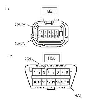
Tester Connection Condition Specified Condition M2-1 (CA2P) - H56-4 (CG) Cable disconnected from negative (-) auxiliary battery terminal 200 Ω or higher M2-6 (CA2N) - H56-4 (CG) Cable disconnected from negative (-) auxiliary battery terminal 200 Ω or higher M2-1 (CA2P) - H56-16 (BAT) Cable disconnected from negative (-) auxiliary battery terminal 6 kΩ or higher M2-6 (CA2N) - H56-16 (BAT) Cable disconnected from negative (-) auxiliary battery terminal 6 kΩ or higher *1 DLC3 *a Front view of wire harness connector
(to Blind Spot Monitor Sensor RH (Slave))Result
Proceed to OK NG
Result:
OK
REPLACE BLIND SPOT MONITOR SENSOR RH (SLAVE). Refer to REMOVAL [12/2019 - 10/2022] , or refer to REMOVAL [10/2022 - 11/2023]
Result:
NG
REPAIR OR REPLACE CAN MAIN WIRE OR CONNECTOR (BLIND SPOT MONITOR SENSOR RH (SLAVE) - NO. 22 CAN JUNCTION CONNECTOR)