Power Source Circuit [12/2019 - 11/2023]: Procedure
- CHECK HARNESS AND CONNECTOR (BLIND SPOT MONITOR SENSOR LH (MASTER) POWER SOURCE)
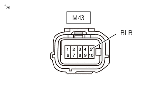
- Disconnect the M43 blind spot monitor sensor LH (master) connector.
- Measure the voltage according to the value(s) in the table below.
Standard Voltage
Tester Connection Switch Condition Specified Condition M43-5 (BLB) - Body ground Ignition switch ON 11 to 14 V*1
10.5 to 16 V*2M43-5 (BLB) - Body ground Ignition switch off Below 1 V *a Front view of wire harness connector
(to Blind Spot Monitor Sensor LH (Master))- *1: w/o Stop and Start System
- *2: w/ Stop and Start System
Result
Result Proceed to OK A NG (w/o Stop and Start System) B NG (w/ Stop and Start System) C
Result:
B
REPAIR OR REPLACE HARNESS OR CONNECTOR
Result:
C
GO TO STOP AND START SYSTEM. Refer to HOW TO PROCEED WITH TROUBLESHOOTING [12/2019 - 10/2022] , or refer to HOW TO PROCEED WITH TROUBLESHOOTING [10/2022 - ]
Result:
A
See step 2
- CHECK HARNESS AND CONNECTOR (BLIND SPOT MONITOR SENSOR LH (MASTER) - BODY GROUND)
- Measure the resistance according to the value(s) in the table below.
Standard Resistance
Tester Connection Condition Specified Condition M43-10 (BLGD) - Body ground Always Below 1 Ω Result
Proceed to OK NG
Result:
NG
REPAIR OR REPLACE HARNESS OR CONNECTOR
Result:
OK
See step 3
- Measure the resistance according to the value(s) in the table below.
- CHECK HARNESS AND CONNECTOR (BLIND SPOT MONITOR SENSOR RH (SLAVE) POWER SOURCE)
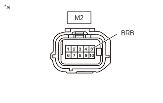
- Disconnect the M2 blind spot monitor sensor RH (slave) connector.
- Measure the voltage according to the value(s) in the table below.
Standard Voltage
Tester Connection Switch Condition Specified Condition M2-5 (BRB) - Body ground Ignition switch ON 11 to 14 V M2-5 (BRB) - Body ground Ignition switch off Below 1 V *a Front view of wire harness connector
(to Blind Spot Monitor Sensor RH (Slave))Result
Proceed to OK NG
Result:
NG
REPAIR OR REPLACE HARNESS OR CONNECTOR
Result:
OK
See step 4
- CHECK HARNESS AND CONNECTOR (BLIND SPOT MONITOR SENSOR RH (SLAVE) - BODY GROUND)
- Measure the resistance according to the value(s) in the table below.
Standard Resistance
Tester Connection Condition Specified Condition M2-10 (BRGD) - Body ground Always Below 1 Ω Result
Proceed to OK NG
Result:
OK
PROCEED TO NEXT SUSPECTED AREA SHOWN IN PROBLEM SYMPTOMS TABLE. Refer to PROBLEM SYMPTOMS TABLE [12/2019 - 10/2022] , or refer to PROBLEM SYMPTOMS TABLE [10/2022 - 11/2023]
Result:
NG
REPAIR OR REPLACE HARNESS OR CONNECTOR
- Measure the resistance according to the value(s) in the table below.