Power Source Circuit [11/2023 - ]: Procedure
- CHECK HARNESS AND CONNECTOR (BLIND SPOT MONITOR SENSOR LH (B) POWER SOURCE)
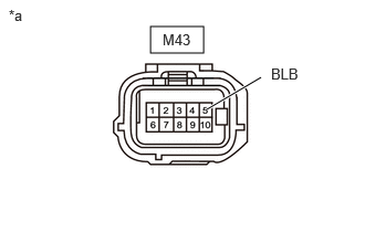
- Disconnect the M43 blind spot monitor sensor LH (B) connector.
- Measure the voltage according to the value(s) in the table below.
Standard Voltage
Tester Connection Switch Condition Specified Condition M43-5 (BLB) - Body ground Ignition switch ON 11 to 14 V M43-5 (BLB) - Body ground Ignition switch off Below 1 V *a Front view of wire harness connector
(to Blind Spot Monitor Sensor LH (B))Result
Proceed to OK NG
Result:
NG
REPAIR OR REPLACE HARNESS OR CONNECTOR
Result:
OK
See step 2
- CHECK HARNESS AND CONNECTOR (BLIND SPOT MONITOR SENSOR LH (B) - BODY GROUND)
- Measure the resistance according to the value(s) in the table below.
Standard Resistance
Tester Connection Condition Specified Condition M43-10 (BLGD) - Body ground Always Below 1 Ω Result
Proceed to OK NG
Result:
NG
REPAIR OR REPLACE HARNESS OR CONNECTOR
Result:
OK
See step 3
- Measure the resistance according to the value(s) in the table below.
- CHECK HARNESS AND CONNECTOR (BLIND SPOT MONITOR SENSOR RH (A) POWER SOURCE)
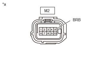
- Disconnect the M2 blind spot monitor sensor RH (A) connector.
- Measure the voltage according to the value(s) in the table below.
Standard Voltage
Tester Connection Switch Condition Specified Condition M2-5 (BRB) - Body ground Ignition switch ON 11 to 14 V M2-5 (BRB) - Body ground Ignition switch off Below 1 V *a Front view of wire harness connector
(to Blind Spot Monitor Sensor RH (A))Result
Proceed to OK NG
Result:
NG
REPAIR OR REPLACE HARNESS OR CONNECTOR
Result:
OK
See step 4
- CHECK HARNESS AND CONNECTOR (BLIND SPOT MONITOR SENSOR RH (A) - BODY GROUND)
- Measure the resistance according to the value(s) in the table below.
Standard Resistance
Tester Connection Condition Specified Condition M2-10 (BRGD) - Body ground Always Below 1 Ω Result
Proceed to OK NG
Result:
OK
PROCEED TO NEXT SUSPECTED AREA SHOWN IN PROBLEM SYMPTOMS TABLE. Refer to PROBLEM SYMPTOMS TABLE [11/2023 - ]
Result:
NG
REPAIR OR REPLACE HARNESS OR CONNECTOR
- Measure the resistance according to the value(s) in the table below.