Inspection [12/2019 - ]: Procedure
- INSPECT DOOR CONTROL SWITCH ASSEMBLY
- Measure the resistance according to the value(s) in the table below.
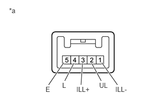
*a Component without harness connected
(Door Control Switch Assembly)Standard Resistance
Tester Connection Condition Specified Condition 4 (L) - 5 (E) Lock switch pushed Below 200 Ω 4 (L) - 5 (E) Lock switch not pushed 1 MΩ or higher 2 (UL) - 5 (E) Unlock switch not pushed 1 MΩ or higher 2 (UL) - 5 (E) Unlock switch pushed Below 200 Ω If the result is not as specified, replace the door control switch assembly.
- Inspect the switch illumination.
- Apply auxiliary battery voltage to the door control switch assembly and check that the switch illuminates.
OK
Measurement Condition Specified Condition Auxiliary battery positive (+) → Terminal 3 (ILL+)
Auxiliary battery negative (-) → Terminal 1 (ILL-)Illuminates If the result is not as specified, replace the door control switch assembly.
- Apply auxiliary battery voltage to the door control switch assembly and check that the switch illuminates.
- Measure the resistance according to the value(s) in the table below.