Power Source Mode does not Change to ON (IG) [12/2019 - 11/2023]: Procedure
- CHECK FOR DTC
- Using the GTS, check for certification ECU (smart key ECU assembly) DTCs.
Body Electrical > Power Source Control > Trouble Codes
Body Electrical > Smart Key > Trouble Codes
Body Electrical > Starting Control > Trouble Codes
Result
Result Proceed to DTCs are not output A Smart key system (for Start Function) DTCs are output B
Result:
B
GO TO DIAGNOSTIC TROUBLE CODE CHART. Refer to DIAGNOSTIC TROUBLE CODE CHART [12/2019 - 10/2021] , or refer to DIAGNOSTIC TROUBLE CODE CHART [10/2021 - 10/2022] , or refer to DIAGNOSTIC TROUBLE CODE CHART [10/2022 - 11/2023]
Result:
A
See step 2
- Using the GTS, check for certification ECU (smart key ECU assembly) DTCs.
- CHECK CERTIFICATION ECU (SMART KEY ECU ASSEMBLY)
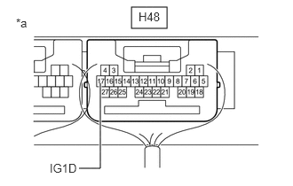
- Measure the voltage according to the value(s) in the table below.
*a Component with harness connected
(Certification ECU (Smart Key ECU Assembly))Standard Voltage
Tester Connection Condition Specified Condition H48-17 (IG1D) - Body ground Ignition switch off → Ignition switch ACC 1 V or less → 9 V or higher Result
Proceed to OK NG
Result:
NG
REPLACE CERTIFICATION ECU (SMART KEY ECU ASSEMBLY). Refer to REMOVAL [12/2019 - 11/2023]
Result:
OK
See step 3
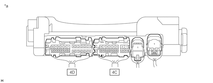
- Measure the voltage according to the value(s) in the table below.
- CHECK HARNESS AND CONNECTOR (CERTIFICATION ECU (SMART KEY ECU ASSEMBLY) - INSTRUMENT PANEL JUNCTION BLOCK ASSEMBLY)
- Disconnect the 4A, 4B, 4E and 4F instrument panel junction block assembly connectors.
- Measure the resistance according to the value(s) in the table below.
Standard Resistance
Tester Connection Condition Specified Condition H48-17 (IG1D) - 4A-17 Always Below 1 Ω 4B-3 - Body ground Always Below 1 Ω H48-17 (IG1D) or 4A-17 - Other terminals and body ground Always 10 kΩ or higher - Measure the voltage according to the value(s) in the table below.
Standard Voltage
Tester Connection Condition Specified Condition 4F-1 - Body ground Always 11 to 14 V 4E-1 - Body ground Always 11 to 14 V Result
Proceed to OK NG
Result:
NG
REPAIR OR REPLACE HARNESS OR CONNECTOR
Result:
OK
See step 4
- CHECK INSTRUMENT PANEL JUNCTION BLOCK ASSEMBLY (IG1-NO. 1, IG1-NO. 2, IG2-NO. 2 RELAY)
- Remove the instrument panel junction block assembly.
Refer to REMOVAL [12/2019 - 10/2022] , or refer to REMOVAL [10/2022 - 11/2023]
- Connect all of the instrument panel junction block assembly connectors.
- Connect the H48 certification ECU (smart key ECU assembly) connector.
- Measure the voltage according to the value(s) in the table below.
*a Component with harness connected
(Instrument Panel Junction Block Assembly)- - Standard Voltage
Tester Connection Condition Specified Condition 4C-14 - Body ground Ignition switch ON 11 to 14 V 4D-12 - Body ground Ignition switch ON 11 to 14 V 4C-15 - Body ground Ignition switch ON 11 to 14 V Result
Proceed to OK NG
Result:
OK
USE SIMULATION METHOD TO CHECK. Refer to HOW TO PROCEED WITH TROUBLESHOOTING [12/2019 - ]
Result:
NG
REPLACE INSTRUMENT PANEL JUNCTION BLOCK ASSEMBLY. Refer to REMOVAL [12/2019 - 10/2022] , or refer to REMOVAL [10/2022 - 11/2023]
- Remove the instrument panel junction block assembly.