Engine does not Start [10/2022 - 11/2023]: Procedure
- CHECK ENGINE CRANKING OPERATION
- Get into the vehicle while carrying an electrical key transmitter sub-assembly.
- Move the shift lever to P.
- Check that the key indicator display is displayed on the multi-information display in the combination meter assembly, and then press the engine switch and check that the engine cranks.
Result
Result Proceed to Engine cranks and initial combustion occurs A Engine cranks but initial combustion does not occur B Engine does not crank C
Result:
A
GO TO OTHER PROBLEM (Immobilizer System does not Operate Properly). Refer to Immobilizer System does not Operate Properly [10/2022 - 11/2023]
Result:
B
GO TO SFI SYSTEM. Refer to HOW TO PROCEED WITH TROUBLESHOOTING [10/2022 - ]
Result:
C
See step 2
- CHECK ENGINE SWITCH CONDITION
- Get into the vehicle while carrying an electrical key transmitter sub-assembly.
- Move the shift lever to P.
- With the brake pedal released, check that pressing the engine switch causes the power source mode to change.
Result
Result Proceed to Power source mode changes: Off → ACC → ON → off A Power source mode does not change to ACC or ON B Power source mode changes to ON but not to ACC C Power source mode changes to ACC but not to ON D
Result:
B
GO TO OTHER PROBLEM (Power Source Mode does not Change to ON (IG and ACC)). Refer to Power Source Mode does not Change to ON (IG and ACC) [10/2022 - 11/2023]
Result:
C
GO TO OTHER PROBLEM (Power Source Mode does not Change to ON (ACC)). Refer to Power Source Mode does not Change to ON (ACC) [12/2019 - 11/2023]
Result:
D
GO TO OTHER PROBLEM (Power Source Mode does not Change to ON (IG)). Refer to Power Source Mode does not Change to ON (IG) [12/2019 - 11/2023]
Result:
A
See step 3
- READ VALUE USING GTS (STOP LIGHT SWITCH1)
- Read the Data List according to the display on the GTS.
Body Electrical > Power Source Control > Data List
Tester Display Measurement Item Range Normal Condition Diagnostic Note Stop Light Switch1 State of brake pedal OFF or ON OFF: Brake pedal released
ON: Brake pedal depressed- Use this item to determine if the stop light switch assembly is malfunctioning.
- The engine cannot be started when this item is OFF.
- If the stop light switch assembly is malfunctioning, the engine can be started by pressing and holding the engine switch for a certain period of time.
Body Electrical > Power Source Control > Data List
Tester Display Stop Light Switch1 OK
The GTS display changes correctly in response to the brake pedal operation.
Result
Proceed to OK NG
Result:
NG
See step 21
Result:
OK
See step 4
- Read the Data List according to the display on the GTS.
- READ VALUE USING GTS (NEUTRAL SW/ CLUTCH SW, SHIFT POSITION P OR N)
- Read the Data List according to the display on the GTS.
Body Electrical > Power Source Control > Data List
Tester Display Measurement Item Range Normal Condition Diagnostic Note Neutral SW/ Clutch SW Shift position (P and N) OFF or ON OFF: Shift lever in any position other than P or N
ON: Shift lever in P or N- Use this item to determine if the park/neutral position switch assembly is malfunctioning.
- When the engine cannot be started due to a park/neutral position switch assembly malfunction, OFF is displayed.
Body Electrical > Power Source Control > Data List
Tester Display Neutral SW/ Clutch SW Body Electrical > Starting Control > Data List
Tester Display Measurement Item Range Normal Condition Diagnostic Note Shift Position P or N Park/Neutral position switch status OFF or ON OFF: Shift lever not in P or N
ON: Shift lever in P or NWhen OFF is displayed, the engine will not crank. Body Electrical > Starting Control > Data List
Tester Display Shift Position P or N OK
The GTS display changes correctly in response to the shift lever operation.
Result
Proceed to OK NG
Result:
NG
See step 19
Result:
OK
See step 5
- Read the Data List according to the display on the GTS.
- READ VALUE USING GTS (STARTER REQUEST SIGNAL)
- Read the Data List according to the display on the GTS.
Body Electrical > Power Source Control > Data List
Tester Display Measurement Item Range Normal Condition Diagnostic Note Starter Request Signal Engine start request signal status OFF or ON OFF: The engine switch is not pressed
ON: With the shift lever in P and the brake pedal depressed, the engine switch is pressed and held- When the engine cannot be started due to a start request signal malfunction, OFF is displayed.
- When the engine switch is pressed, the duration of time that ON is displayed will be extremely short. As such, the engine switch needs to be pressed and held for a certain period of time.
Body Electrical > Power Source Control > Data List
Tester Display Starter Request Signal NOTE:Check that the key indicator display is displayed on the multi-information display in the combination meter assembly, and then press the engine switch.
OK
The GTS display changes correctly in response to the engine switch operation.
Result
Proceed to OK NG
Result:
NG
See step 17
Result:
OK
See step 6
- Read the Data List according to the display on the GTS.
- READ VALUE USING GTS (STARTER REQUEST SIGNAL)
- Get into the vehicle while carrying an electrical key transmitter sub-assembly.
- Move the shift lever to P.
- According to the display on the GTS, read the Data List while pressing the engine switch with the brake pedal depressed.
Body Electrical > Starting Control > Data List
Tester Display Measurement Item Range Normal Condition Diagnostic Note Starter SW Starter operation request OFF or ON OFF: Starter operation not requested
ON: Starter operation requestedWhen OFF is displayed, the engine will not crank. Body Electrical > Starting Control > Data List
Tester Display Starter SW OK
The GTS display changes.
Result
Proceed to OK NG
Result:
NG
REPLACE CERTIFICATION ECU (SMART KEY ECU ASSEMBLY). Refer to REMOVAL [12/2019 - 11/2023]
Result:
OK
See step 7
- INSPECT ST RELAY
Refer to ON-VEHICLE INSPECTION [10/2022 - ]
Result
Proceed to OK NG Result:
NG
REPLACE ST RELAY
Result:
OK
See step 8
- CHECK HARNESS AND CONNECTOR (CERTIFICATION ECU (SMART KEY ECU ASSEMBLY) - ST RELAY)
- Measure the voltage according to the value(s) in the table below.
Standard Voltage
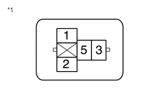
Tester Connection Condition Specified Condition No. 1 engine room relay block and No. 1 junction block assembly ST relay terminal 2 - Body ground Engine switch pressed and held with brake pedal depressed (starter on) → Approximately 1 second after engine switch released (starter off) 6 V or higher* → 1.0 V or less *1 No. 1 Engine Room Relay Block and No. 1 Junction Block Assembly
(ST Relay Holder)HINT:
*: While the engine is cranking, the auxiliary battery voltage may drop to approximately 6 V.
Result
Proceed to OK NG
Result:
NG
See step 12
Result:
OK
See step 9
- Measure the voltage according to the value(s) in the table below.
- CHECK HARNESS AND CONNECTOR (ST RELAY - AUXILIARY BATTERY AND GROUND)
- Measure the resistance according to the value(s) in the table below.
Standard Resistance
Tester Connection Condition Specified Condition No. 1 engine room relay block and No. 1 junction block assembly ST relay terminal 1 - Body ground Always Below 1 Ω *1 No. 1 Engine Room Relay Block and No. 1 Junction Block Assembly
(ST Relay Holder) - Measure the voltage according to the value(s) in the table below.
Standard Voltage
Tester Connection Condition Specified Condition No. 1 engine room relay block and No. 1 junction block assembly ST relay terminal 5 - Body ground Always 11 to 14 V Result
Proceed to OK NG
Result:
NG
REPAIR OR REPLACE HARNESS OR CONNECTOR
Result:
OK
See step 10
- Measure the resistance according to the value(s) in the table below.
- CHECK HARNESS AND CONNECTOR (STARTER ASSEMBLY - ST RELAY)
- Disconnect the C56 starter assembly connector.
- Measure the resistance according to the value(s) in the table below.
Standard Resistance
W/ STOP AND START SYSTEM:Tester Connection Condition Specified Condition No. 1 engine room relay block and No. 1 junction block assembly ST relay terminal 3 - C56-1 (ST) Always Below 1 Ω No. 1 engine room relay block and No. 1 junction block assembly ST relay terminal 3 or C56-1 (ST) - Other terminals and body ground Always 10 kΩ or higher W/O STOP AND START SYSTEM:Tester Connection Condition Specified Condition No. 1 engine room relay block and No. 1 junction block assembly ST relay terminal 3 - C60-2 (SL1) Always Below 1 Ω No. 1 engine room relay block and No. 1 junction block assembly ST relay terminal 3 or C60-2 (SL1) - Other terminals and body ground Always 10 kΩ or higher Result
Proceed to OK NG
Result:
NG
REPAIR OR REPLACE HARNESS OR CONNECTOR
Result:
OK
See step 11
- CHECK HARNESS AND CONNECTOR (STARTER ASSEMBLY - AUXILIARY BATTERY)
- Disconnect the C69 starter assembly connector.
- Measure the voltage according to the value(s) in the table below.
Standard Voltage
Tester Connection Condition Specified Condition C69-1 (B) - Body ground Always 11 to 14 V Result
Proceed to OK NG
Result:
OK
REPLACE STARTER ASSEMBLY
w/ Stop and Start System: Refer to REMOVAL [10/2022 - 11/2023]
w/o Stop and Start System: Refer to REMOVAL [10/2022 - 11/2023]
Result:
NG
REPAIR OR REPLACE HARNESS OR CONNECTOR
- CHECK CERTIFICATION ECU (SMART KEY ECU ASSEMBLY)
- Measure the voltage according to the value(s) in the table below.
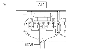
*a Component with harness connected
(Certification ECU (Smart Key ECU Assembly))Standard Voltage
Tester Connection Condition Specified Condition A19-9 (STAR) - Body ground Engine switch pressed and held with brake pedal depressed (starter on) → Approximately 1 second after engine switch released (starter off) 6 V or higher* → 1.0 V or less HINT:
*: While the engine is cranking, the auxiliary battery voltage may drop to approximately 6 V.
Result
Proceed to OK NG
Result:
NG
REPLACE CERTIFICATION ECU (SMART KEY ECU ASSEMBLY). Refer to REMOVAL [12/2019 - 11/2023]
Result:
OK
See step 13
- Measure the voltage according to the value(s) in the table below.
- CHECK HARNESS AND CONNECTOR (CERTIFICATION ECU (SMART KEY ECU ASSEMBLY) - PARK/NEUTRAL POSITION SWITCH ASSEMBLY)
- Disconnect the A19 certification ECU (smart key ECU assembly) connector.
- Disconnect the C52 park/neutral position switch assembly connector.
- Measure the resistance according to the value(s) in the table below.
Standard Resistance
Tester Connection Condition Specified Condition A19-9 (STAR) - C52-4 (B) Always Below 1 Ω A19-9 (STAR) or C52-4 (B) - Other terminals and body ground Always 10 kΩ or higher Result
Proceed to OK NG
Result:
NG
REPAIR OR REPLACE HARNESS OR CONNECTOR
Result:
OK
See step 14
- CHECK CERTIFICATION ECU (SMART KEY ECU ASSEMBLY)
- Install the ST relay to the No. 1 engine room relay block and No. 1 junction block assembly.
- Measure the voltage according to the value(s) in the table below.
Standard Voltage
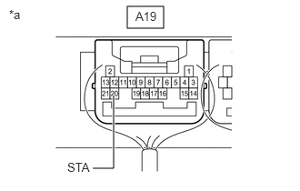
Tester Connection Condition Specified Condition A19-20 (STA) - Body ground Engine switch pressed and held with brake pedal depressed (starter on) → Approximately 1 second after engine switch released (starter off) 6 V or higher* → 1.0 V or less *a Component with harness connected
(Certification ECU (Smart Key ECU Assembly))HINT:
*: While the engine is cranking, the auxiliary battery voltage may drop to approximately 6 V.
Result
Proceed to OK NG
Result:
NG
REPLACE CERTIFICATION ECU (SMART KEY ECU ASSEMBLY). Refer to REMOVAL [12/2019 - 11/2023]
Result:
OK
See step 15
- CHECK HARNESS AND CONNECTOR (CERTIFICATION ECU (SMART KEY ECU ASSEMBLY) - ST RELAY)
- Disconnect the A19 certification ECU (smart key ECU assembly) connector.
- Measure the resistance according to the value(s) in the table below.
Standard Resistance
Tester Connection Condition Specified Condition A19-20 (STA) - 2 (ST relay) Always Below 1 Ω A19-20 (STA) or 2 (ST relay) - Other terminals and body ground Always 10 kΩ or higher Result
Proceed to OK NG
Result:
NG
REPAIR OR REPLACE HARNESS OR CONNECTOR
Result:
OK
See step 16
- CHECK HARNESS AND CONNECTOR (PARK/NEUTRAL POSITION SWITCH ASSEMBLY - ST RELAY)
- Measure the resistance according to the value(s) in the table below.
Standard Resistance
Tester Connection Condition Specified Condition C52-9 (L) - 2 (ST relay) Always Below 1 Ω C52-9 (L) or 2 (ST relay) - Other terminals and body ground Always 10 kΩ or higher Result
Proceed to OK NG
Result:
OK
GO TO SFI SYSTEM. Refer to HOW TO PROCEED WITH TROUBLESHOOTING [10/2022 - ]
Result:
NG
REPAIR OR REPLACE HARNESS OR CONNECTOR
- Measure the resistance according to the value(s) in the table below.
- REPLACE CERTIFICATION ECU (SMART KEY ECU ASSEMBLY)
- Temporarily replace the certification ECU (smart key ECU assembly) with a new one and register the electrical key transmitter sub-assemblies.
HINT:
Refer to Registration.
Refer to REGISTRATION [10/2022 - 11/2023]
Result
Proceed to NEXT
Result:
NEXT
See step 18
- Temporarily replace the certification ECU (smart key ECU assembly) with a new one and register the electrical key transmitter sub-assemblies.
- CHECK WHETHER ENGINE STARTS
Result:
OK
END (CERTIFICATION ECU (SMART KEY ECU ASSEMBLY) WAS DEFECTIVE)
Result:
NG
REPLACE ID CODE BOX (IMMOBILIZER CODE ECU). Refer to REMOVAL [10/2022 - 11/2023]
- INSPECT PARK/NEUTRAL POSITION SWITCH ASSEMBLY
Refer to INSPECTION [10/2022 - ]
Result
Proceed to OK NG Result:
NG
REPLACE PARK/NEUTRAL POSITION SWITCH ASSEMBLY. Refer to REMOVAL [10/2022 - 11/2023]
Result:
OK
See step 20
- CHECK HARNESS AND CONNECTOR (CERTIFICATION ECU (SMART KEY ECU ASSEMBLY) - PARK/NEUTRAL POSITION SWITCH ASSEMBLY)
- Disconnect the A19 certification ECU (smart key ECU assembly) connector.
- Measure the resistance according to the value(s) in the table below.
Standard Resistance
Tester Connection Condition Specified Condition A19-9 (STAR) - C52-4 (B) Always Below 1 Ω A19-9 (STAR) or C52-4 (B) - Other terminals and body ground Always 10 kΩ or higher Result
Proceed to OK NG
Result:
OK
REPLACE CERTIFICATION ECU (SMART KEY ECU ASSEMBLY). Refer to REMOVAL [12/2019 - 11/2023]
Result:
NG
REPAIR OR REPLACE HARNESS OR CONNECTOR
- INSPECT STOP LIGHT SWITCH ASSEMBLY
Refer to ON-VEHICLE INSPECTION [12/2019 - ]
Result
Proceed to OK NG Result:
NG
REPLACE STOP LIGHT SWITCH ASSEMBLY. Refer to REMOVAL [12/2019 - ]
Result:
OK
See step 22
- CHECK HARNESS AND CONNECTOR (CERTIFICATION ECU (SMART KEY ECU ASSEMBLY) - STOP LIGHT SWITCH ASSEMBLY)
- Disconnect the M5 certification ECU (smart key ECU assembly) connector.
- Disconnect the A42 stop light switch assembly connector.
- Disconnect the A83 ECM connector.
- Disconnect the A39 skid control ECU (brake actuator assembly) connector.
- Disconnect the H28 shift lock control unit assembly connector.
- Measure the resistance according to the value(s) in the table below.
Standard Resistance
Tester Connection Condition Specified Condition M5-25 (STP1) - A42-3 (L) Always Below 1 Ω M5-25 (STP1) or A42-3 (L) - Other terminals and body ground Always 10 kΩ or higher Result
Proceed to OK NG
Result:
OK
REPLACE CERTIFICATION ECU (SMART KEY ECU ASSEMBLY). Refer to REMOVAL [12/2019 - 11/2023]
Result:
NG
REPAIR OR REPLACE HARNESS OR CONNECTOR