DTC B27A1-13: Driver Side Electrical Antenna Circuit Open [11/2023 - ]: Procedure
- CHECK CONNECTOR CONNECTION
- Check that the connectors are properly connected to the certification ECU (smart key ECU assembly) and front door outside handle assembly (for driver door).
OK
Connectors are properly connected.
Result
Proceed to OK NG
Result:
NG
CONNECT CONNECTORS PROPERLY
Result:
OK
See step 2
- Check that the connectors are properly connected to the certification ECU (smart key ECU assembly) and front door outside handle assembly (for driver door).
- CHECK HARNESS AND CONNECTOR (CERTIFICATION ECU (SMART KEY ECU ASSEMBLY) - FRONT DOOR OUTSIDE HANDLE ASSEMBLY (FOR DRIVER DOOR))
Pre-procedure1
- Disconnect the H138 certification ECU (smart key ECU assembly) connector.
- Disconnect the J36 front door outside handle assembly (for driver door) connector.
Procedure1
- Measure the resistance according to the value(s) in the table below.
Standard Resistance
Tester Connection Condition Specified Condition H138-16 (CLG1) - J36-4 (ANT1) Always Below 1 Ω H138-15 (CG1B) - J36-6 (ANT2) Always Below 1 Ω Result
Proceed to OK NG Post-procedure1
- Connect the H138 certification ECU (smart key ECU assembly) connector.
Result:
NG
REPAIR OR REPLACE HARNESS OR CONNECTOR
Result:
OK
See step 3
- CHECK CERTIFICATION ECU (SMART KEY ECU ASSEMBLY) (OUTPUT TO FRONT DOOR OUTSIDE HANDLE ASSEMBLY (FOR DRIVER DOOR))
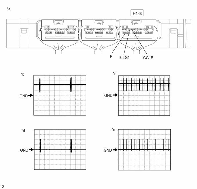
- Using an oscilloscope, check the waveform.
*a Component with harness connected
(Certification ECU (Smart Key ECU Assembly))*b Waveform 1 *c Waveform 2 *d Waveform 3 *e Waveform 4 - - OK
Tester Connection Condition Tool Setting Specified Condition H138-16 (CLG1) - H138-29 (E) Procedure: - Ignition switch off
- All doors closed
- Electrical key transmitter sub-assembly not inside vehicle
- All doors locked through wireless operation (electrical key transmitter sub-assembly brought inside detection area*)
5 V/DIV., 500 ms./DIV. Pulse generation
(See waveform 1)Procedure: - Ignition switch off
- All doors closed
- Electrical key transmitter sub-assembly not inside vehicle
- All doors locked through wireless operation (electrical key transmitter sub-assembly brought outside detection area*)
5 V/DIV., 500 ms./DIV. Pulse generation
(See waveform 2)H138-15 (CG1B) - H138-29 (E) Procedure: - Ignition switch off
- All doors closed
- Electrical key transmitter sub-assembly not inside vehicle
- All doors locked through wireless operation (electrical key transmitter sub-assembly brought inside detection area*)
5 V/DIV., 500 ms./DIV. Pulse generation
(See waveform 3)Procedure: - Ignition switch off
- All doors closed
- Electrical key transmitter sub-assembly not inside vehicle
- All doors locked through wireless operation (electrical key transmitter sub-assembly brought outside detection area*)
5 V/DIV., 500 ms./DIV. Pulse generation
(See waveform 4)HINT:
*: For details about the entry function detection area, refer to Operation Check.
Refer to OPERATION CHECK [11/2023 - ]
Result
Proceed to OK NG
Result:
OK
REPLACE FRONT DOOR OUTSIDE HANDLE ASSEMBLY (FOR DRIVER DOOR). Refer to DISASSEMBLY [11/2023 - ]
Result:
NG
REPLACE CERTIFICATION ECU (SMART KEY ECU ASSEMBLY). Refer to REMOVAL [11/2023 - ]
- Using an oscilloscope, check the waveform.