All Doors LOCK/UNLOCK Functions do not Operate Via Door Control Switch [12/2019 - 11/2023]: Procedure
- READ VALUE USING GTS (Door Lock SW-Lock, Door Lock SW-Unlock)
- Read the Data List according to the display on the GTS.
Body Electrical > Main Body > Data List
Tester Display Measurement Item Range Normal Condition Diagnostic Note Door Lock SW-Lock Door control switch assembly lock signal OFF or ON OFF: Lock switch of door control switch assembly not pushed
ON: Lock switch of door control switch assembly pushed- Door Lock SW-Unlock Door control switch assembly unlock signal OFF or ON OFF: Unlock switch of door control switch assembly not pushed
ON: Unlock switch of door control switch assembly pushed- Body Electrical > Main Body > Data List
Tester Display Door Lock SW-Lock Door Lock SW-Unlock OK
The GTS indicates ON or OFF according to the switch operation shown in the table.
Result
Proceed to OK NG
Result:
OK
REPLACE MAIN BODY ECU (MULTIPLEX NETWORK BODY ECU). Refer to REMOVAL [12/2019 - 10/2022] , or refer to REMOVAL [10/2022 - 11/2023]
Result:
NG
See step 2
- Read the Data List according to the display on the GTS.
- INSPECT DOOR CONTROL SWITCH ASSEMBLY
Refer to INSPECTION [12/2019 - ]
Result
Proceed to OK NG Result:
NG
REPLACE DOOR CONTROL SWITCH ASSEMBLY. Refer to REMOVAL [12/2019 - ]
Result:
OK
See step 3
- CHECK HARNESS AND CONNECTOR (DOOR CONTROL SWITCH ASSEMBLY - INSTRUMENT PANEL JUNCTION BLOCK ASSEMBLY AND BODY GROUND)
- Disconnect the 4A and 4B instrument panel junction block assembly connectors.
- Measure the resistance according to the value(s) in the table below.
Standard Resistance
Tester Connection Condition Specified Condition J4-2 (UL) - 4A-39 Always Below 1 Ω J4-4 (L) - 4B-16 Always Below 1 Ω J4-5 (E) - Body ground Always Below 1 Ω 4A-39 or J4-2 (UL) - Other terminals and body ground Always 10 kΩ or higher 4B-16 or J4-4 (L) - Other terminals and body ground Always 10 kΩ or higher Result
Proceed to OK NG
Result:
NG
REPAIR OR REPLACE HARNESS OR CONNECTOR
Result:
OK
See step 4
- INSPECT INSTRUMENT PANEL JUNCTION BLOCK ASSEMBLY
- Remove the instrument panel junction block assembly.
Refer to REMOVAL [12/2019 - 10/2022] , or refer to REMOVAL [10/2022 - 11/2023]
- Remove the main body ECU (multiplex network body ECU).
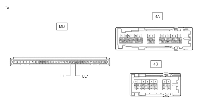
*a Component without harness connected
(Instrument Panel Junction Block Assembly)- - - Measure the resistance according to the value(s) in the table below.
Standard Resistance
Tester Connection Condition Specified Condition MB-22 (UL1) - 4A-39 Always Below 1 Ω MB-20 (L1) - 4B-16 Always Below 1 Ω Result
Proceed to OK NG
Result:
OK
REPLACE MAIN BODY ECU (MULTIPLEX NETWORK BODY ECU). Refer to REMOVAL [12/2019 - 10/2022] , or refer to REMOVAL [10/2022 - 11/2023]
Result:
NG
REPLACE INSTRUMENT PANEL JUNCTION BLOCK ASSEMBLY. Refer to REMOVAL [12/2019 - 10/2022] , or refer to REMOVAL [10/2022 - 11/2023]
- Remove the instrument panel junction block assembly.