Power Back Door cannot be Operated Using Any Switch [10/2022 - 11/2023]: Procedure
- CHECK COMBINATION METER ASSEMBLY
- Check that the shift position indicator operates correctly and the speedometer indicates 0 km/h (0 mph) when the vehicle is stopped with the hybrid control system started.
OK
Combination meter operates normally
Result
Proceed to OK NG
Result:
NG
GO TO METER / GAUGE SYSTEM
except 12.3 Inch Display: Refer to HOW TO PROCEED WITH TROUBLESHOOTING [12/2019 - ]
for 12.3 Inch Display: Refer to HOW TO PROCEED WITH TROUBLESHOOTING [10/2022 - ]
Result:
OK
See step 2
- Check that the shift position indicator operates correctly and the speedometer indicates 0 km/h (0 mph) when the vehicle is stopped with the hybrid control system started.
- CHECK FOR DTC
- Check for DTCs.
Body Electrical > Back Door > Trouble Codes
OK
DTC is not output
Result
Proceed to OK NG
Result:
NG
GO TO DIAGNOSTIC TROUBLE CODE CHART. Refer to DIAGNOSTIC TROUBLE CODE CHART [12/2019 - 11/2023]
Result:
OK
See step 3
- Check for DTCs.
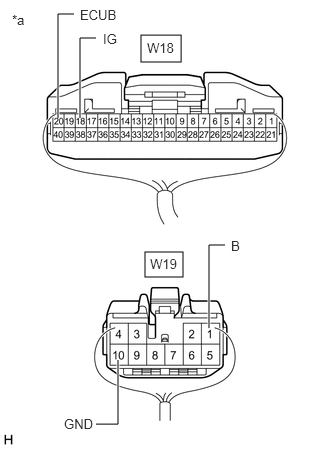
- CHECK HARNESS AND CONNECTOR (MULTIPLEX NETWORK DOOR ECU - AUXILIARY BATTERY AND BODY GROUND)
- Measure the resistance according to the value(s) in the table below.
*a Rear view of wire harness connector
(to Multiplex Network Door ECU)Standard Resistance
Tester Connection Condition Specified Condition W19-10 (GND) - Body ground Always Below 1 Ω - Measure the voltage according to the value(s) in the table below.
Standard Voltage
Tester Connection Condition Specified Condition W18-20 (ECUB) - Body ground Ignition switch off*1
Always*211 to 14 V W19-1 (B) - Body ground Ignition switch off*1
Always*211 to 14 V W18-18 (IG) - Body ground Ignition switch ON 11 to 14 V Ignition switch off Below 1 V - *1: for HV Model
- *2: for Gasoline Model
Result
Proceed to OK NG
Result:
NG
REPAIR OR REPLACE HARNESS OR CONNECTOR
Result:
OK
See step 4
- Measure the resistance according to the value(s) in the table below.
- READ VALUE USING GTS (PBD MAIN SW)
- Read the Data List according to the display on the GTS.
Body Electrical > Back Door > Data List
Tester Display Measurement Item Range Normal Condition Diagnostic Note PBD Main SW Power back door ON/OFF signal OFF or ON Customize setting displayed - Body Electrical > Back Door > Data List
Tester Display PBD Main SW OK
The display is as specified in the normal condition column.
Result
Proceed to OK NG
Result:
NG
GO TO METER / GAUGE SYSTEM
except 12.3 Inch Display: Refer to HOW TO PROCEED WITH TROUBLESHOOTING [12/2019 - ]
for 12.3 Inch Display: Refer to HOW TO PROCEED WITH TROUBLESHOOTING [10/2022 - ]
Result:
OK
See step 5
- Read the Data List according to the display on the GTS.
- READ VALUE USING GTS (PBD TOUCH SENSOR)
- Read the Data List according to the display on the GTS.
Body Electrical > Back Door > Data List
Tester Display Measurement Item Range Normal Condition Diagnostic Note PBD Touch Sensor (Right) Power back door sensor assembly RH signal OFF, ON or Open OFF: Power back door sensor assembly RH not pressed
ON: Power back door sensor assembly RH pressed
Open: Power back door sensor assembly RH circuit open- PBD Touch Sensor (Left) Power back door sensor assembly LH signal OFF, ON or Open OFF: Power back door sensor assembly LH not pressed
ON: Power back door sensor assembly LH pressed
Open: Power back door sensor assembly LH circuit open- Body Electrical > Back Door > Data List
Tester Display PBD Touch Sensor (Right) PBD Touch Sensor (Left) Result
Result Proceed to The values of Data List items "PBD Touch Sensor (Right)" and "PBD Touch Sensor (Left)" change to "ON" or "OFF" in accordance with the operation of the sensors. A The value of Data List item "PBD Touch Sensor (Right)" does not change to "ON" or "OFF" in accordance with the operation of the power back door sensor assembly RH. B The value of Data List item "PBD Touch Sensor (Left)" does not change to "ON" or "OFF" in accordance with the operation of the power back door sensor assembly LH. C
Result:
A
REPLACE MULTIPLEX NETWORK DOOR ECU. Refer to REMOVAL [12/2019 - 11/2023]
Result:
C
See step 8
Result:
B
See step 6
- Read the Data List according to the display on the GTS.
- INSPECT POWER BACK DOOR SENSOR ASSEMBLY RH
Refer to INSPECTION [12/2019 - ]
Result
Proceed to OK NG Result:
NG
REPLACE POWER BACK DOOR SENSOR ASSEMBLY RH. Refer to REMOVAL [12/2019 - ]
Result:
OK
See step 7
- CHECK HARNESS AND CONNECTOR (POWER BACK DOOR SENSOR ASSEMBLY RH - MULTIPLEX NETWORK DOOR ECU)
- Disconnect the W18 multiplex network door ECU connector.
- Measure the resistance according to the value(s) in the table below.
Standard Resistance
Tester Connection Condition Specified Condition W9-1 (OSR) - W18-6 (OSR) Always Below 1 Ω W9-2 (OSRE) - W18-24 (OSE) Always Below 1 Ω W9-1 (OSR) or W18-6 (OSR) - Body ground Always 10 kΩ or higher W9-2 (OSRE) or W18-24 (OSE) - Body ground Always 10 kΩ or higher Result
Proceed to OK NG
Result:
OK
REPLACE MULTIPLEX NETWORK DOOR ECU. Refer to REMOVAL [12/2019 - 11/2023]
Result:
NG
REPAIR OR REPLACE HARNESS OR CONNECTOR
- INSPECT POWER BACK DOOR SENSOR ASSEMBLY LH
Refer to INSPECTION [12/2019 - ]
Result
Proceed to OK NG Result:
NG
REPLACE POWER BACK DOOR SENSOR ASSEMBLY LH. Refer to REMOVAL [12/2019 - ]
Result:
OK
See step 9
- CHECK HARNESS AND CONNECTOR (POWER BACK DOOR SENSOR ASSEMBLY LH - MULTIPLEX NETWORK DOOR ECU)
- Disconnect the W18 multiplex network door ECU connector.
- Measure the resistance according to the value(s) in the table below.
Standard Resistance
Tester Connection Condition Specified Condition W10-1 (OSL) - W18-26 (OSL) Always Below 1 Ω W10-2 (OSLE) - W18-24 (OSE) Always Below 1 Ω W10-1 (OSL) or W18-26 (OSL) - Body ground Always 10 kΩ or higher W10-2 (OSLE) or W18-24 (OSE) - Body ground Always 10 kΩ or higher Result
Proceed to OK NG
Result:
OK
REPLACE MULTIPLEX NETWORK DOOR ECU. Refer to REMOVAL [12/2019 - 11/2023]
Result:
NG
REPAIR OR REPLACE HARNESS OR CONNECTOR