Power Back Door cannot be Operated Using Any Switch [11/2023 - ]: Procedure
- CHECK VEHICLE CONDITION
- Operate the multi-information display in the combination meter assembly and check the customization status.
Display Description Default Setting Relevant ECU System Settings Function that enables/disables the power back door. ON ON or OFF Multiplex network door ECU Result
Result Proceed to Customization item is "ON" (power back door system operation is possible) A Customization item is "OFF" (power back door system operation is prohibited) B
Result:
B
PERFORM CUSTOMIZE SETTING
Refer to CUSTOMIZE PARAMETERS [11/2023 - ]
Result:
A
See step 2
- Operate the multi-information display in the combination meter assembly and check the customization status.
- CHECK CUSTOMIZE SETTING (UNLOCK KEY TWICE FUNCTION)
- Read the customize setting "Unlock Key Twice Function" according to the display on the GTS.
Refer to CUSTOMIZE PARAMETERS [11/2023 - ]
Result
Result Proceed to The customize setting is "Disable" A The customize setting is "Enable" B
Result:
B
PERFORM CUSTOMIZE SETTING
Refer to CUSTOMIZE PARAMETERS [11/2023 - ]
Result:
A
See step 3
- Read the customize setting "Unlock Key Twice Function" according to the display on the GTS.
- CHECK CUSTOMIZE SETTING (WIRELESS UNLOCK TWICE FUNCTION)
- Read the customize setting "Wireless Unlock Twice Function" according to the display on the GTS.
Refer to CUSTOMIZE PARAMETERS [11/2023 - ]
Result
Result Proceed to The customize setting is "Disable" A The customize setting is "Enable" B
Result:
B
PERFORM CUSTOMIZE SETTING
Refer to CUSTOMIZE PARAMETERS [11/2023 - ]
Result:
A
See step 4
- Read the customize setting "Wireless Unlock Twice Function" according to the display on the GTS.
- CHECK CUSTOMIZE SETTING (ENTRY UNLOCK TWICE FUNCTION)
- Read the customize setting "Entry Unlock Twice Function" according to the display on the GTS.
Refer to CUSTOMIZE PARAMETERS [11/2023 - ]
Result
Result Proceed to The customize setting is "Disable" A The customize setting is "Enable" B
Result:
B
PERFORM CUSTOMIZE SETTING
Refer to CUSTOMIZE PARAMETERS [11/2023 - ]
Result:
A
See step 5
- Read the customize setting "Entry Unlock Twice Function" according to the display on the GTS.
- CHECK FOR DTC
- Check for DTCs.
Body Electrical > Back Door > Trouble Codes
OK
DTC is not output
Result
Proceed to OK NG
Result:
NG
GO TO DIAGNOSTIC TROUBLE CODE CHART
Refer to DIAGNOSTIC TROUBLE CODE CHART [11/2023 - ]
Result:
OK
See step 6
- Check for DTCs.
- READ VALUE USING GTS
- Read the Data List according to the display on the GTS.
Body Electrical > Back Door > Data List
Tester Display Measurement Item Range Normal Condition Diagnostic Note Half Latch Switch Latch switch signal ON or OFF Back door opened condition: ON
Back door closed condition: OFF- Closer Position Switch Initial switch signal ON or OFF Back door opened condition: ON
Back door closed condition: ON- Pawl Switch Pawl switch signal ON or OFF Back door opened condition: OFF
Back door closed condition: OFF- Courtesy Switch Back door courtesy switch signal ON or OFF Back door opened condition: ON
Back door closed condition: OFF- Body Electrical > Back Door > Data List
Tester Display Half Latch Switch Closer Position Switch Pawl Switch Courtesy Switch Result
Result Proceed to The ON/OFF switches normally depending on the back door condition (open or close). A The ON/OFF not switches normally depending on the back door condition (open or close). B
Result:
B
See step 18
Result:
A
See step 7
- Read the Data List according to the display on the GTS.
- CHECK POWER BACK DOOR SYSTEM CONDITION
- Check the power back door system condition.
Result
Result Proceed to Power back door does not operate normally A Power back door operates normally B
Result:
B
GO TO POWER BACK DOOR CANNOT BE OPERATED FREQUENTLY
Refer to Power Back Door cannot be Operated Frequently [11/2023 - ]
Result:
A
See step 8
- Check the power back door system condition.
- CHECK COMBINATION METER FUNCTION
- Operation check
- Check that the shift position indicator light in the combination meter assembly operates correctly in accordance with the operation of the shift lever.
- Confirm that the speedometer indicates 0 km/h when the vehicle is stopped.
OK
The meter and gauge system operates correctly.
Result
Proceed to OK NG
Result:
NG
GO TO METER / GAUGE SYSTEM
for 12.3 Inch Display: Refer to HOW TO PROCEED WITH TROUBLESHOOTING [10/2022 - ]
except 12.3 Inch Display: Refer to HOW TO PROCEED WITH TROUBLESHOOTING [12/2019 - ]
Result:
OK
See step 9
- Operation check
- CHECK HARNESS AND CONNECTOR (MULTIPLEX NETWORK DOOR ECU - AUXILIARY BATTERY AND BODY GROUND)
- Disconnect the W30, W28 and W27 multiplex network door ECU connectors.
- Measure the resistance according to the value(s) in the table below.
Standard Resistance
Tester Connection Condition Specified Condition W28-4 (GND) - Body ground Always Below 1 Ω - Measure the voltage according to the value(s) in the table below.
Standard Voltage
Tester Connection Condition Specified Condition W30-7 (ECUB) - Body ground Ignition switch off 11 to 14 V*1 10.5 to 16 V*2 W27-5 (B) - Body ground Ignition switch off 11 to 14 V*1 10.5 to 16 V*2 W30-9 (IG) - Body ground Ignition switch off Below 1 V Ignition switch ON 11 to 14 V - *1: w/o Stop and Start System
- *2: w/ Stop and Start System
Result
Proceed to OK NG
Result:
NG
REPAIR OR REPLACE HARNESS OR CONNECTOR
Result:
OK
See step 10
- READ VALUE USING GTS
- Read the Data List according to the display on the GTS.
Body Electrical > Back Door > Data List
Tester Display Measurement Item Range Normal Condition Diagnostic Note PBD Main Switch Power back door ON/OFF signal ON or OFF Current customize setting displayed - Door Lock Signal Back door condition signal Lock or Unlock Lock: Back door locked
Unlock: Back door unlocked- Body Electrical > Back Door > Data List
Tester Display PBD Main Switch Door Lock Signal Result
Result Proceed to Either item is normal A "PBD Main SW" item does not switch to "ON" or "OFF" according to customize setting B "Door Lock Signal" item does not switch to "Lock" or "Unlock" according to operation to lock or unlock all doors C
Result:
B
GO TO METER / GAUGE SYSTEM
for 12.3 Inch Display: Refer to HOW TO PROCEED WITH TROUBLESHOOTING [10/2022 - ]
except 12.3 Inch Display: Refer to HOW TO PROCEED WITH TROUBLESHOOTING [12/2019 - ]
Result:
C
See step 16
Result:
A
See step 11
- Read the Data List according to the display on the GTS.
- READ VALUE USING GTS
- Read the Data List according to the display on the GTS.
Body Electrical > Back Door > Data List
Tester Display Measurement Item Range Normal Condition Diagnostic Note PBD Touch Sensor RH Power back door sensor assembly RH signal ON, OFF or Open ON: Power back door sensor assembly RH pressed
OFF: Power back door sensor assembly RH not pressed
Open: Power back door sensor assembly RH circuit open- PBD Touch Sensor LH Power back door sensor assembly LH signal ON, OFF or Open ON: Power back door sensor assembly LH pressed
OFF: Power back door sensor assembly LH not pressed
Open: Power back door sensor assembly LH circuit open- Body Electrical > Back Door > Data List
Tester Display PBD Touch Sensor RH PBD Touch Sensor LH Result
Result Proceed to On the GTS screen, ON or OFF is displayed accordingly A On the GTS screen, ON or OFF is not displayed accordingly or Open is displayed for power back door sensor assembly RH B On the GTS screen, ON or OFF is not displayed accordingly or Open is displayed for power back door sensor assembly LH C
Result:
A
REPLACE MULTIPLEX NETWORK DOOR ECU
Refer to REMOVAL [11/2023 - ]
Result:
C
See step 14
Result:
B
See step 12
- Read the Data List according to the display on the GTS.
- INSPECT POWER BACK DOOR SENSOR ASSEMBLY RH
Refer to INSPECTION [12/2019 - ]
Result
Proceed to OK NG Result:
NG
REPLACE POWER BACK DOOR SENSOR ASSEMBLY RH
Refer to REMOVAL [11/2023 - ]
Result:
OK
See step 13
- CHECK HARNESS AND CONNECTOR (POWER BACK DOOR SENSOR ASSEMBLY RH - MULTIPLEX NETWORK DOOR ECU)
- Disconnect the W9 power back door sensor assembly RH connector.
- Disconnect the W29 multiplex network door ECU connector.
- Measure the resistance according to the value(s) in the table below.
Standard Resistance
Tester Connection Condition Specified Condition W9-1 (OSR) - W29-8 (OSR) Always Below 1 Ω W9-2 (OSRE) - W29-9 (OSE) Always Below 1 Ω W9-1 (OSR) or W29-8 (OSR) - Body ground Always 10 kΩ or higher W9-2 (OSRE) or W29-9 (OSE) - Body ground Always 10 kΩ or higher Result
Proceed to OK NG
Result:
OK
REPLACE MULTIPLEX NETWORK DOOR ECU
Refer to REMOVAL [11/2023 - ]
Result:
NG
REPAIR OR REPLACE HARNESS OR CONNECTOR
- INSPECT POWER BACK DOOR SENSOR ASSEMBLY LH
Refer to INSPECTION [12/2019 - ]
Result
Proceed to OK NG Result:
NG
REPLACE POWER BACK DOOR SENSOR ASSEMBLY LH
Refer to REMOVAL [12/2019 - ]
Result:
OK
See step 15
- CHECK HARNESS AND CONNECTOR (POWER BACK DOOR SENSOR ASSEMBLY LH - MULTIPLEX NETWORK DOOR ECU)
- Disconnect the W10 power back door sensor assembly LH connector.
- Disconnect the W29 multiplex network door ECU connector.
- Measure the resistance according to the value(s) in the table below.
Standard Resistance
Tester Connection Condition Specified Condition W10-1 (OSL) - W29-1 (OSL) Always Below 1 Ω W10-2 (OSLE) - W29-9 (OSE) Always Below 1 Ω W10-1 (OSL) or W29-1 (OSL) - Body ground Always 10 kΩ or higher W10-2 (OSLE) or W29-9 (OSE) - Body ground Always 10 kΩ or higher Result
Proceed to OK NG
Result:
OK
REPLACE MULTIPLEX NETWORK DOOR ECU
Refer to REMOVAL [11/2023 - ]
Result:
NG
REPAIR OR REPLACE HARNESS OR CONNECTOR
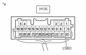
- CHECK HARNESS AND CONNECTOR (MAIN BODY ECU (MULTIPLEX NETWORK BODY ECU) - MULTIPLEX NETWORK DOOR ECU)
- Disconnect the H135 main body ECU (multiplex network body ECU) connector.
- Disconnect the W30 multiplex network door ECU connector.
- Measure the resistance according to the value(s) in the table below.
Standard Resistance
Tester Connection Condition Specified Condition H135-7 (LSBO) - W30-11 (LIB) Always Below 1 Ω H135-7 (LSBO) or W30-11 (LIB) - Body ground Always 10 kΩ or higher Result
Proceed to OK NG
Result:
NG
REPAIR OR REPLACE HARNESS OR CONNECTOR
Result:
OK
See step 17
- CHECK MAIN BODY ECU (MULTIPLEX NETWORK BODY ECU)
- Remove the main body ECU (multiplex network body ECU) with the connector(s) still connected.
*a Component with harness connected
(Main Body ECU (Multiplex Network Body ECU)) - Measure the voltage according to the value(s) in the table below.
Standard Voltage
Tester Connection Condition Specified Condition H135-7 (LSBO) - Body ground Back door unlocked Below 1 V Result
Proceed to OK NG
Result:
OK
REPLACE MULTIPLEX NETWORK DOOR ECU
Refer to REMOVAL [11/2023 - ]
Result:
NG
REPLACE MAIN BODY ECU (MULTIPLEX NETWORK BODY ECU)
Refer to REMOVAL [11/2023 - ]
- Remove the main body ECU (multiplex network body ECU) with the connector(s) still connected.
- INSPECT BACK DOOR LOCK WITH COURTESY LIGHT SWITCH ASSEMBLY
Refer to INSPECTION [12/2019 - ]
Result
Proceed to OK NG Result:
NG
REPLACE BACK DOOR LOCK WITH COURTESY LIGHT SWITCH ASSEMBLY
Refer to REMOVAL [12/2019 - ]
Result:
OK
See step 19
- CHECK HARNESS AND CONNECTOR (MULTIPLEX NETWORK DOOR ECU - BACK DOOR LOCK WITH COURTESY LIGHT SWITCH ASSEMBLY)
- Disconnect the W28 multiplex network door ECU connector.
- Disconnect the W13 back door lock with courtesy light switch assembly connector.
- Measure the resistance according to the value(s) in the table below.
Standard Resistance
Tester Connection Condition Specified Condition W28-2 (DC+) - W13-2 (M+) Always Below 1 Ω W28-6 (DC-) - W13-1 (M-) Always Below 1 Ω W28-2 (DC+) or W13-2 (M+) - Body ground Always 10 kΩ or higher W28-6 (DC-) or W13-1 (M-) - Body ground Always 10 kΩ or higher Result
Proceed to OK NG
Result:
OK
REPLACE MULTIPLEX NETWORK DOOR ECU
Refer to REMOVAL [11/2023 - ]
Result:
NG
REPAIR OR REPLACE HARNESS OR CONNECTOR