DTC B2220-49: Back Door Motor Internal Electronic Failure [11/2023 - ]: Procedure
- CLEAR DTC
Result:
NEXT
See step 2
- REPRODUCE DTC
Result:
NEXT
See step 3
- CHECK FOR DTC
- Check for DTCs.
Body Electrical > Back Door > Trouble Codes
Result
Result Proceed to B2220-49 is output A B2220-49 is not output B
Result:
B
USE SIMULATION METHOD TO CHECK. Refer to HOW TO PROCEED WITH TROUBLESHOOTING [12/2019 - ]
Result:
A
See step 4
- Check for DTCs.
- INSPECT POWER BACK DOOR UNIT ASSEMBLY SET LH
Pre-procedure1
- Fully open the back door.
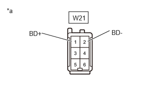
- Disconnect the W21 power back door unit assembly set LH connector.
*a Component without harness connected
(Power Back Door Unit Assembly Set LH)Procedure1
- Measure the resistance according to the value(s) in the table below.
Standard Resistance
Tester Connection Condition Specified Condition W21-1 (BD+) - Body ground Always 10 kΩ or higher W21-2 (BD-) - Body ground Always 10 kΩ or higher W21-1 (BD+) - W21-2 (BD-) Always Below 1 MΩ Result
Proceed to OK NG Post-procedure1
- None
Result:
NG
REPLACE POWER BACK DOOR UNIT ASSEMBLY SET LH. Refer to REMOVAL [12/2019 - ]
Result:
OK
See step 5
- INSPECT POWER BACK DOOR UNIT ASSEMBLY SET RH
Pre-procedure1
- Fully open the back door.
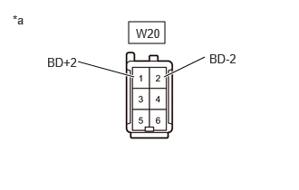
- Disconnect the W20 power back door unit assembly set RH connector.
*a Component without harness connected
(Power Back Door Unit Assembly Set RH)Procedure1
- Measure the resistance according to the value(s) in the table below.
Standard Resistance
Tester Connection Condition Specified Condition W20-1 (BD+2) - Body ground Always 10 kΩ or higher W20-2 (BD-2) - Body ground Always 10 kΩ or higher W20-1 (BD+2) - W20-2 (BD-2) Always Below 1 MΩ Result
Proceed to OK NG Post-procedure1
- None
Result:
NG
REPLACE POWER BACK DOOR UNIT ASSEMBLY SET RH. Refer to REMOVAL [12/2019 - ]
Result:
OK
See step 6
- CHECK HARNESS AND CONNECTOR (MULTIPLEX NETWORK DOOR ECU - POWER BACK DOOR UNIT ASSEMBLY SET LH)
Pre-procedure1
- Disconnect the W27 multiplex network door ECU connector.
- Disconnect the W21 power back door unit assembly set LH connector.
Procedure1
- Measure the resistance according to the value(s) in the table below.
Standard Resistance
Tester Connection Condition Specified Condition W27-1 (BD+) - W21-1 (BD+) Always Below 1 Ω W27-3 (BD-) - W21-2 (BD-) Always Below 1 Ω W27-1 (BD+) or W21-1 (BD+) - Body ground Always 10 kΩ or higher W27-3 (BD-) or W21-2 (BD-) - Body ground Always 10 kΩ or higher Result
Proceed to OK NG Post-procedure1
- None
Result:
NG
REPAIR OR REPLACE HARNESS OR CONNECTOR
Result:
OK
See step 7
- CHECK HARNESS AND CONNECTOR (MULTIPLEX NETWORK DOOR ECU - POWER BACK DOOR UNIT ASSEMBLY SET RH)
Pre-procedure1
- Disconnect the W27 multiplex network door ECU connector.
- Disconnect the W20 power back door unit assembly set RH connector.
Procedure1
- Measure the resistance according to the value(s) in the table below.
Standard Resistance
Tester Connection Condition Specified Condition W27-6 (BD+2) - W20-1 (BD+2) Always Below 1 Ω W27-8 (BD-2) - W20-2 (BD-2) Always Below 1 Ω W27-6 (BD+2) or W20-1 (BD+2) - Body ground Always 10 kΩ or higher W27-8 (BD-2) or W20-2 (BD-2) - Body ground Always 10 kΩ or higher Result
Proceed to OK NG Post-procedure1
- None
Result:
OK
REPLACE MULTIPLEX NETWORK DOOR ECU. Refer to REMOVAL [11/2023 - ]
Result:
NG
REPAIR OR REPLACE HARNESS OR CONNECTOR