DTC B2226-31: PBD Unit Pulse Sensor LH Circuit No Signal [11/2023 - ]: Procedure
- CLEAR DTC
Result:
NEXT
See step 2
- REPRODUCE DTC
Result:
NEXT
See step 3
- CHECK FOR DTC
- Check for DTCs.
Body Electrical > Back Door > Trouble Codes
Result
Result Proceed to B2226-31 is output A B2226-31 is not output B
Result:
B
USE SIMULATION METHOD TO CHECK
Refer to HOW TO PROCEED WITH TROUBLESHOOTING [12/2019 - ]
Result:
A
See step 4
- Check for DTCs.
- CHECK HARNESS AND CONNECTOR (MULTIPLEX NETWORK DOOR ECU - POWER BACK DOOR UNIT ASSEMBLY SET LH)
Pre-procedure1
- Disconnect the W29 multiplex network door ECU connector.
- Disconnect the W21 power back door unit assembly set LH connector.
Procedure1
- Measure the resistance according to the value(s) in the table below.
Standard Resistance
Tester Connection Condition Specified Condition W29-11 (DSG) - W21-4 (DSG) Always Below 1 Ω W29-4 (DSV) - W21-3 (DSV) Always Below 1 Ω W29-5 (DS2) - W21-6 (DS2) Always Below 1 Ω W29-13 (DS1) - W21-5 (DS1) Always Below 1 Ω W29-11 (DSG) or W21-4 (DSG) - Body ground Always 10 kΩ or higher W29-4 (DSV) or W21-3 (DSV) - Body ground Always 10 kΩ or higher W29-5 (DS2) or W21-6 (DS2) - Body ground Always 10 kΩ or higher W29-13 (DS1) or W21-5 (DS1) - Body ground Always 10 kΩ or higher Result
Proceed to OK NG Post-procedure1
- None
Result:
NG
REPAIR OR REPLACE HARNESS OR CONNECTOR
Result:
OK
See step 5
- CHECK MULTIPLEX NETWORK DOOR ECU
Pre-procedure1
- Disconnect the cable from the negative (-) auxiliary battery terminal.
- Disconnect the W21 power back door unit assembly set LH connector.
Procedure1
- Measure the resistance according to the value(s) in the table below.
Standard Resistance
Tester Connection Condition Specified Condition W21-4 (DSG) - Body ground Always Below 1 Ω Pre-procedure2
- Connect the cable to the negative (-) auxiliary battery terminal.
Procedure2
- Measure the voltage according to the value(s) in the table below.
Standard Voltage
Tester Connection Condition Specified Condition W21-5 (DS1) - Body ground Ignition switch off 7 V or higher W21-6 (DS2) - Body ground Ignition switch off 7 V or higher W21-3 (DSV) - Body ground Ignition switch off 7 V or higher Result
Proceed to OK NG Post-procedure1
- None
Result:
NG
REPLACE MULTIPLEX NETWORK DOOR ECU
Refer to REMOVAL [11/2023 - ]
Result:
OK
See step 6
- CHECK POWER BACK DOOR UNIT ASSEMBLY SET LH
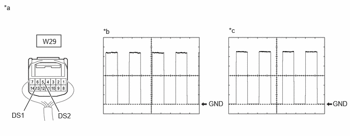
- Using an oscilloscope, check the waveform of each terminal from the rear of the multiplex network door ECU connector.
*a Component with harness connected
(Multiplex Network Door ECU)*b Waveform (CH1) *c Waveform (CH2) - - Measurement Condition
Item Condition Tester Connection - CH1: W29-13 (DS1) - Body ground
- CH2: W29-5 (DS2) - Body ground
Tool Setting 2 V/DIV., 2 ms./DIV. Vehicle Condition Open and close the back door by hand. HINT:
- The period changes in accordance with the speed at which the back door is opened and closed by hand.
- The wave height changes in accordance with the auxiliary battery voltage.
Result
Proceed to OK NG
Result:
OK
REPLACE MULTIPLEX NETWORK DOOR ECU
Refer to REMOVAL [11/2023 - ]
Result:
NG
REPLACE POWER BACK DOOR UNIT ASSEMBLY SET LH
Refer to REMOVAL [12/2019 - ]
- Using an oscilloscope, check the waveform of each terminal from the rear of the multiplex network door ECU connector.