Back Door Closer does not Operate [12/2019 - 11/2023]: Procedure
- CHECK FOR DTC
- Check for DTCs.
Body Electrical > Back Door > Trouble Codes
Result
Result Proceed to DTC is not output A DTC B2250 is output B DTC B2251 is output C
Result:
B
GO TO DTC B2250. Refer to DTC B2250: Back Door Closer Operation Malfunction [12/2019 - 11/2023]
Result:
C
GO TO DTC B2251. Refer to DTC B2251: Back Door Closer Switch Malfunction [12/2019 - 11/2023]
Result:
A
See step 2
- Check for DTCs.
- CHECK BACK DOOR LOCK FUNCTION
- Check if the back door can be fully closed by hand.
Result
Result Proceed to The back door can be closed normally A The back door cannot be closed normally B
Result:
B
IMPROPER FIT OF BACK DOOR, OR A FOREIGN OBJECT IS STUCK IN BACK DOOR
Result:
A
See step 3
- Check if the back door can be fully closed by hand.
- INITIALIZE POWER BACK DOOR SYSTEM
- Initialize the power back door system.
Refer to INITIALIZATION [12/2019 - 11/2023]
Result
Proceed to NEXT
Result:
NEXT
See step 4
- Initialize the power back door system.
- CHECK BACK DOOR CLOSER
- When the back door is partially closed, check that the motor operates to fully close the back door.
Result
Result Proceed to The back door closer operates normally A The back door closer does not operate normally B
Result:
A
END (BACK DOOR CLOSER HAS NOT BEEN INITIALIZED)
Result:
B
See step 5
- When the back door is partially closed, check that the motor operates to fully close the back door.
- CHECK HARNESS AND CONNECTOR (MULTIPLEX NETWORK DOOR ECU - AUXILIARY BATTERY AND BODY GROUND)
- Measure the resistance according to the value(s) in the table below.
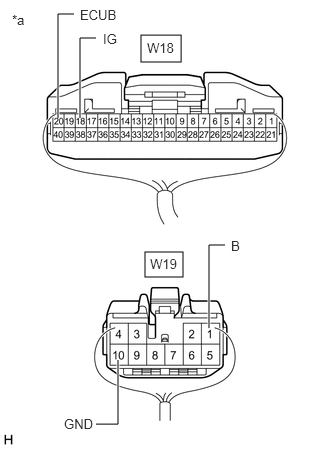
*a Rear view of wire harness connector
(to Multiplex Network Door ECU)Standard Resistance
Tester Connection Condition Specified Condition W19-10 (GND) - Body ground Always Below 1 Ω - Measure the voltage according to the value(s) in the table below.
Standard Voltage
Tester Connection Condition Specified Condition W18-20 (ECUB) - Body ground Ignition switch off*1
Always*211 to 14 V W19-1 (B) - Body ground Ignition switch off*1
Always*211 to 14 V W18-18 (IG) - Body ground Ignition switch ON 11 to 14 V Ignition switch off Below 1 V - *1: for HV Model
- *2: for Gasoline Model
Result
Proceed to OK NG
Result:
NG
REPAIR OR REPLACE HARNESS OR CONNECTOR
Result:
OK
See step 6
- Measure the resistance according to the value(s) in the table below.
- INSPECT BACK DOOR LOCK WITH COURTESY LIGHT SWITCH ASSEMBLY
Refer to INSPECTION [12/2019 - ]
Result
Proceed to OK NG Result:
NG
REPLACE BACK DOOR LOCK WITH COURTESY LIGHT SWITCH ASSEMBLY. Refer to REMOVAL [12/2019 - ]
Result:
OK
See step 7
- CHECK HARNESS AND CONNECTOR (BACK DOOR LOCK WITH COURTESY LIGHT SWITCH ASSEMBLY - MULTIPLEX NETWORK DOOR ECU AND BODY GROUND)
- Disconnect the W18 and W19 multiplex network door ECU connectors.
- Measure the resistance according to the value(s) in the table below.
Standard Resistance
Tester Connection Condition Specified Condition W13-2 (M+) - W19-4 (DC+) Always Below 1 Ω W13-1 (M-) - W19-3 (DC-) Always Below 1 Ω W14-4 (CTY) - W18-11 (FUL) Always Below 1 Ω W14-2 (FSW) - W18-13 (PAWL) Always Below 1 Ω W14-3 (CLS) - W18-9 (HAF) Always Below 1 Ω W14-6 (OPN) - W18-7 (POS) Always Below 1 Ω W14-1 (E) - Body ground Always Below 1 Ω W13-2 (M+) or W19-4 (DC+) - Body ground Always 10 kΩ or higher W13-1 (M-) or W19-3 (DC-) - Body ground Always 10 kΩ or higher W14-4 (CTY) or W18-11 (FUL) - Body ground Always 10 kΩ or higher W14-2 (FSW) or W18-13 (PAWL) - Body ground Always 10 kΩ or higher W14-3 (CLS) or W18-9 (HAF) - Body ground Always 10 kΩ or higher W14-6 (OPN) or W18-7 (POS) - Body ground Always 10 kΩ or higher Result
Proceed to OK NG
Result:
OK
REPLACE MULTIPLEX NETWORK DOOR ECU. Refer to REMOVAL [12/2019 - 11/2023]
Result:
NG
REPAIR OR REPLACE HARNESS OR CONNECTOR