Power Back Door Warning System does not Operate [12/2019 - 11/2023]: Procedure
- CHECK OPERATION
- Check power back door system operation.
Refer to OPERATION CHECK [12/2019 - 11/2023]
Result
Result Proceed to Hazard warning light does not come on A Power back door warning buzzer does not operate B
Result:
B
See step 6
Result:
A
See step 2
- Check power back door system operation.
- CHECK WIRELESS DOOR LOCK CONTROL SYSTEM (HAZARD ANSWER-BACK FUNCTION)
- Check wireless door lock operation.
Refer to OPERATION CHECK [12/2019 - 11/2023]
OK
Hazard answer-back function operates normally.
Result
Proceed to OK NG
Result:
NG
GO TO WIRELESS DOOR LOCK CONTROL SYSTEM. Refer to HOW TO PROCEED WITH TROUBLESHOOTING [12/2019 - 11/2023]
Result:
OK
See step 3
- Check wireless door lock operation.
- REPLACE MULTIPLEX NETWORK DOOR ECU
- Temporarily replace the multiplex network door ECU with a new or known good one.
Refer to REMOVAL [12/2019 - 11/2023]
Result
Proceed to NEXT
Result:
NEXT
See step 4
- Temporarily replace the multiplex network door ECU with a new or known good one.
- INITIALIZE POWER BACK DOOR SYSTEM
- Initialize the power back door system.
Refer to INITIALIZATION [12/2019 - 11/2023]
Result
Proceed to NEXT
Result:
NEXT
See step 5
- Initialize the power back door system.
- CHECK POWER BACK DOOR SYSTEM
- Check that the power back door hazard warning lights operate normally.
Refer to OPERATION CHECK [12/2019 - 11/2023]
OK
The power back door hazard warning lights operate normally.
Result
Proceed to OK NG
Result:
OK
END (MULTIPLEX NETWORK DOOR ECU WAS DEFECTIVE)
Result:
NG
REPLACE MAIN BODY ECU (MULTIPLEX NETWORK BODY ECU). Refer to REMOVAL [12/2019 - 10/2022] , or refer to REMOVAL [10/2022 - 11/2023]
- Check that the power back door hazard warning lights operate normally.
- PERFORM ACTIVE TEST USING GTS (PBD BUZZER)
- Perform the Active Test according to the display on the GTS.
Body Electrical > Back Door > Active Test
Tester Display Measurement Item Control Range Diagnostic Note PBD Buzzer Power back door warning buzzer sound OFF or ON - Body Electrical > Back Door > Active Test
Tester Display PBD Buzzer OK
Power back door warning buzzer sounds
Result
Proceed to OK NG
Result:
OK
REPLACE MULTIPLEX NETWORK DOOR ECU. Refer to REMOVAL [12/2019 - 11/2023]
Result:
NG
See step 7
- Perform the Active Test according to the display on the GTS.
- INSPECT MULTIPLEX NETWORK DOOR ECU
- Disconnect the M44 power back door warning buzzer connector.
- Perform the Active Test according to the display on the GTS.
Body Electrical > Back Door > Active Test
Tester Display Measurement Item Control Range Diagnostic Note PBD Buzzer Power back door warning buzzer sound OFF or ON - Body Electrical > Back Door > Active Test
Tester Display PBD Buzzer - Measure the voltage according to the value(s) in the table below.
Standard Voltage
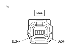
Tester Connection Condition Specified Condition M44-1 (BZR+) - M44-2 (BZR-) Active Test PBD Buzzer is OFF Below 1 V Active Test PBD Buzzer is ON Pulse generation
(frequency: 2 kHz, high voltage: 11 to 14 V, low voltage: below 1 V)*a Front view of wire harness connector
(to Power Back Door Warning Buzzer)Result
Proceed to OK NG
Result:
OK
REPLACE POWER BACK DOOR WARNING BUZZER. Refer to REMOVAL [12/2019 - ]
Result:
NG
See step 8
- CHECK HARNESS AND CONNECTOR (POWER BACK DOOR WARNING BUZZER - MULTIPLEX NETWORK DOOR ECU AND BODY GROUND)
- Disconnect the W18 multiplex network door ECU connector.
- Measure the resistance according to the value(s) in the table below.
Standard Resistance
Tester Connection Condition Specified Condition M44-1 (BZR+) - W18-16 (BZR+) Always Below 1 Ω M44-2 (BZR-) - Body ground Always Below 1 Ω M44-1 (BZR+) or W18-16 (BZR+) - Body ground Always 10 kΩ or higher Result
Proceed to OK NG
Result:
OK
REPLACE MULTIPLEX NETWORK DOOR ECU. Refer to REMOVAL [12/2019 - 11/2023]
Result:
NG
REPAIR OR REPLACE HARNESS OR CONNECTOR