Power Back Door cannot be Operated Using Kick Sensor [12/2019 - 11/2023]: Procedure
- CHECK FOR DTC
- Check for DTCs.
Body Electrical > Back Door > Trouble Codes
OK
DTC is not output.
Result
Proceed to OK NG
Result:
NG
GO TO DIAGNOSTIC TROUBLE CODE CHART. Refer to DIAGNOSTIC TROUBLE CODE CHART [12/2019 - 11/2023]
Result:
OK
See step 2
- Check for DTCs.
- READ VALUE USING GTS
- Read the Data List according to the display on the GTS.
Body Electrical > Back Door > Data List
Tester Display Measurement Item Range Normal Condition Diagnostic Note Kick Sensor Error Status of the kick door control sensor error Normal or Error Normal: Kick door control sensor is normal
Error: Kick door control sensor is abnormal- Body Electrical > Back Door > Data List
Tester Display Kick Sensor Error OK
On the display, Normal is displayed.
Result
Proceed to OK NG
Result:
NG
REPLACE KICK DOOR CONTROL SENSOR. Refer to REMOVAL [12/2019 - 10/2022] , or refer to REMOVAL [10/2022 - 11/2023]
Result:
OK
See step 3
- Read the Data List according to the display on the GTS.
- READ VALUE USING GTS
- Read the Data List according to the display on the GTS.
Body Electrical > Back Door > Data List
Tester Display Measurement Item Range Normal Condition Diagnostic Note Kick Sensor Detection Status of the kick door control sensor detection OFF or ON OFF: Kick door control sensor not detecting a foot
ON: Kick door control sensor detecting a foot- Body Electrical > Back Door > Data List
Tester Display Kick Sensor Detection OK
The display is as specified in the normal condition column.
Result
Proceed to OK NG
Result:
NG
See step 5
Result:
OK
See step 4
- Read the Data List according to the display on the GTS.
- CHECK HARNESS AND CONNECTOR (KICK DOOR CONTROL SENSOR - INSTRUMENT PANEL JUNCTION BLOCK ASSEMBLY)
- Disconnect the V7*1 or V8*2 kick door control sensor connector.
- *1: w/o Towing Hitch
- *2: w/ Towing Hitch
- Disconnect the 4B instrument panel junction block assembly connector.
- Measure the resistance according to the value(s) in the table below.
Standard Resistance
W/O TOWING HITCHTester Connection Condition Specified Condition V7-6 (LIN) - 4B-17 Always Below 1 Ω V7-6 (LIN) or 4B-17 - Body ground Always 10 kΩ or higher W/ TOWING HITCHTester Connection Condition Specified Condition V8-6 (LIN) - 4B-17 Always Below 1 Ω V8-6 (LIN) or 4B-17 - Body ground Always 10 kΩ or higher Result
Proceed to OK NG
Result:
OK
REPLACE KICK DOOR CONTROL SENSOR. Refer to REMOVAL [12/2019 - 10/2022] , or refer to REMOVAL [10/2022 - 11/2023]
Result:
NG
REPAIR OR REPLACE HARNESS OR CONNECTOR
- Disconnect the V7*1 or V8*2 kick door control sensor connector.
- CHECK HARNESS AND CONNECTOR (KICK DOOR CONTROL SENSOR - AUXILIARY BATTERY AND BODY GROUND)
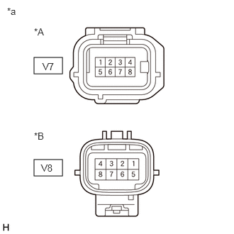
- Disconnect the V7*1 or V8*2 kick door control sensor connector.
*A w/o Towing Hitch *B w/ Towing Hitch *a Front view of wire harness connector
(to Kick Door Control Sensor)- *1: w/o Towing Hitch
- *2: w/ Towing Hitch
- Measure the resistance according to the value(s) in the table below.
Standard Resistance
W/O TOWING HITCHTester Connection Condition Specified Condition V7-7 (GND) - Body ground Always Below 1 Ω W/ TOWING HITCHTester Connection Condition Specified Condition V8-7 (GND) - Body ground Always Below 1 Ω - Measure the voltage according to the value(s) in the table below.
Standard Voltage
W/O TOWING HITCHTester Connection Condition Specified Condition V7-2 (B) - Body ground Ignition switch off*1
Always*211 to 14 V W/ TOWING HITCHTester Connection Condition Specified Condition V8-2 (B) - Body ground Ignition switch off*1
Always*211 to 14 V - *1: for HV Model
- *2: for Gasoline Model
Result
Proceed to OK NG
Result:
NG
REPAIR OR REPLACE HARNESS OR CONNECTOR
Result:
OK
See step 6
- Disconnect the V7*1 or V8*2 kick door control sensor connector.
- CHECK HARNESS AND CONNECTOR (KICK DOOR CONTROL SENSOR - MULTIPLEX NETWORK DOOR ECU)
- Disconnect the W18 multiplex network door ECU connector.
- Measure the resistance according to the value(s) in the table below.
Standard Resistance
W/O TOWING HITCHTester Connection Condition Specified Condition V7-3 (KSOT) - W18-14 (KSIN) Always Below 1 Ω V7-3 (KSOT) or W18-14 (KSIN) - Body ground Always 10 kΩ or higher W/ TOWING HITCHTester Connection Condition Specified Condition V8-3 (KSOT) - W18-14 (KSIN) Always Below 1 Ω V8-3 (KSOT) or W18-14 (KSIN) - Body ground Always 10 kΩ or higher Result
Proceed to OK NG
Result:
NG
REPAIR OR REPLACE HARNESS OR CONNECTOR
Result:
OK
See step 7
- CHECK MULTIPLEX NETWORK DOOR ECU
- Remove the multiplex network door ECU with the connector(s) still connected.
Refer to REMOVAL [12/2019 - 11/2023]
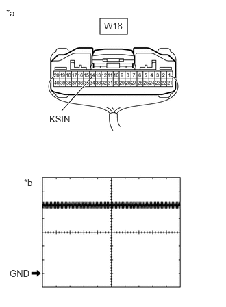
- Check the signal waveform according to the condition(s) in the table below.
*a Component with harness connected
(Multiplex Network Door ECU)*b Waveform MEASUREMENT CONDITIONItem Condition Tester Connection W18-14 (KSIN) - Body ground Tool Setting 2 V/DIV., 50 ms/DIV. Vehicle Condition Kick door control sensor not detecting a foot OK
The waveform displayed is as shown in the illustration.
Result
Proceed to OK NG
Result:
OK
REPLACE KICK DOOR CONTROL SENSOR. Refer to REMOVAL [12/2019 - 10/2022] , or refer to REMOVAL [10/2022 - 11/2023]
Result:
NG
REPLACE MULTIPLEX NETWORK DOOR ECU. Refer to REMOVAL [12/2019 - 11/2023]
- Remove the multiplex network door ECU with the connector(s) still connected.