Terminals Of Ecu [11/2023 - ]
- CHECK MULTIPLEX NETWORK DOOR ECU
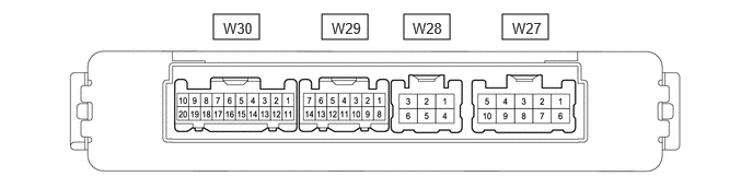
- Disconnect the W27, W28 and W30 multiplex network door ECU connectors.
- Measure the voltage and resistance according to the value(s) in the table below.
Terminal No. (Symbol) Terminal Description Condition Specified Condition W30-9 (IG) - Body ground IG power supply Ignition switch ON 11 to 14 V Ignition switch off Below 1 V W30-7 (ECUB) - Body ground Auxiliary battery power supply Ignition switch off 11 to 14 V W27-5 (B) - Body ground Auxiliary battery power supply Ignition switch off 11 to 14 V W28-4 (GND) - Body ground Body ground Always Below 1 Ω - Reconnect the W27, W28 and W30 multiplex network door ECU connectors.
- Measure the voltage and waveform according to the value(s) in the table below.
Terminal No. (Symbol) Terminal Description Condition Specified Condition W28-2 (DC+) - W28-6 (DC-) Back door lock assembly (back door lock motor) circuit Back door lock motor operating 11 to 14 V Back door lock motor not operating Below 1 V W29-1 (OSL) - W29-9 (OSE) Power back door sensor assembly LH signal Power back door sensor assembly LH not pressed 2 to 3 V Power back door sensor assembly LH pressed Below 1 V W29-3 (DSV2) - Body ground Power back door unit assembly set RH (door sensor) power supply Always 7 V or higher W29-4 (DSV) - Body ground Power back door unit assembly set LH (door sensor) power supply Always 7 V or higher W29-5 (DS2) - Body ground Power back door unit assembly set LH (door sensor) signal Power back door not operating 0 V or 7 V or higher Power back door operating Pulse generation
(See waveform 2)W29-6 (DS12) - Body ground Power back door unit assembly set RH (door sensor) signal Power back door not operating 0 V or 7 V or higher Power back door operating Pulse generation
(See waveform 1)W29-8 (OSR) - W29-9 (OSE) Power back door sensor assembly RH signal Power back door sensor assembly RH not pressed 2 to 3 V Power back door sensor assembly RH pressed Below 1 V W29-10 (DSG2) - Body ground Power back door unit assembly set RH (door sensor) ground Always Below 1 V W29-11 (DSG) - Body ground Power back door unit assembly set LH (door sensor) ground Always Below 1 V W29-12 (DS22) - Body ground Power back door unit assembly set RH (door sensor) signal Power back door not operating 0 V or 7 V or higher Power back door operating Pulse generation
(See waveform 2)W29-13 (DS1) - Body ground Power back door unit assembly set LH (door sensor) signal Power back door not operating 0 V or 7 V or higher Power back door operating Pulse generation
(See waveform 1)W30-1 (BZR+) - Body ground Power back door warning buzzer signal Power back door warning buzzer sounding Pulse generation Power back door warning buzzer not sounding Below 1 V W30-3 (FUL) - Body ground Back door lock with courtesy light switch assembly input Back door open Below 1 V Back door closed Pulse generation W30-5 (HAF) - Body ground Back door lock with courtesy light switch assembly lock signal Back door closed 11 to 14 V Back door fully open Below 1 V W30-11 (LIB) - Body ground Back door lock with courtesy light switch assembly lock signal Back door is locked 11 to 14 V Back door is unlocked Below 1 V W30-13 (PAWL) - Body ground Back door lock with courtesy light switch assembly lock signal Back door fully open 11 to 14 V Back door ajar Below 1 V Back door closed 11 to 14 V A certain amount of time after back door closed Below 1 V W30-14 (BDDN) - Body ground No. 1 power back door control switch signal No. 1 power back door control switch on Below 1 V No. 1 power back door control switch off Pulse generation W30-15 (POS) - Body ground Back door lock with courtesy light switch assembly signal Back door open Below 1 V Back door closer operating 11 to 14 V Operation complete Below 1 V W30-12 (KSIN) - Body ground* Kick detection signal Kick door control sensor not detecting a foot → detecting a foot Pulse generation
(See waveform 3)- *: w/ Hands Free Power Back Door
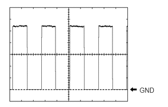
- Using an oscilloscope, check waveform 1.WAVEFORM 1 (REFERENCE)
Item Condition Tester Connection - W29-13 (DS1) - Body ground
- W29-6 (DS12) - Body ground
Tool Setting 2 V/DIV., 2 ms./DIV. Vehicle Condition Power back door operating HINT:
- The period changes in accordance with the speed at which the power back door is opened and closed.
- The wave height changes in accordance with the auxiliary battery voltage.
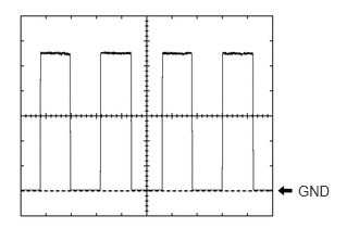
- Using an oscilloscope, check waveform 2.WAVEFORM 2 (REFERENCE)
Item Condition Tester Connection - W29-5 (DS2) - Body ground
- W29-12 (DS22) - Body ground
Tool Setting 2 V/DIV., 2 ms./DIV. Vehicle Condition Power back door operating HINT:
- The period changes in accordance with the speed at which the power back door is opened and closed.
- The wave height changes in accordance with the auxiliary battery voltage.
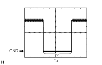
- Using an oscilloscope, check waveform 3.WAVEFORM 3 (REFERENCE)
Item Condition Tester Connection W30-12 (KSIN) - Body ground Tool setting 2 V/DIV., 50 ms/DIV. Vehicle condition Kick door control sensor not detecting a foot → detecting a foot *a Kick detection signal
- CHECK CERTIFICATION ECU (SMART KEY ECU ASSEMBLY)
Refer to TERMINALS OF ECU [11/2023 - ]
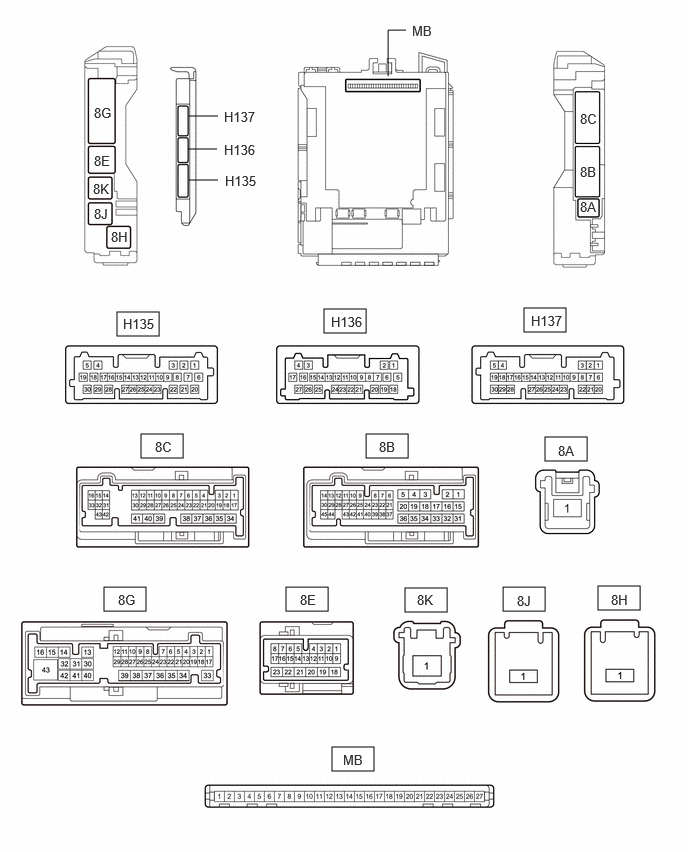
- CHECK MAIN BODY ECU (MULTIPLEX NETWORK BODY ECU) AND POWER DISTRIBUTION BOX ASSEMBLY NOTE:
When disconnecting a wire harness of any component connected to the supply power of the integrated capacitor (integration control supply) or when removing the integrated capacitor (integration control supply), make sure to wait 5 minutes or more after turning the ignition switch off for self-diagnosis to complete and the voltage of the integrated capacitor (integration control supply) to discharge.
- Remove the main body ECU (multiplex network body ECU) from the power distribution box assembly.
Refer to REMOVAL [11/2023 - ]
- Connect the power distribution box assembly connectors.
- Measure the resistance and voltage according to the value(s) in the table below.
Terminal No. (Symbol) Terminal Description Condition Specified Condition MB-13 (GND1) - Body ground Ground Always Below 1 Ω MB-26 (BECU) - Body ground Auxiliary battery power supply Ignition switch off*1
Always*211 to 14 V MB-27 (IGR) - Body ground Ignition power supply (IG signal) Ignition switch off Below 1 V Ignition switch ON 11 to 14 V - *1: for HV Model
- *2: for Gasoline Model
- Install the main body ECU (multiplex network body ECU).
Refer to INSTALLATION [11/2023 - ]
- Measure the voltage and check for pulses according to the value(s) in the table below.
Terminal No. (Symbol) Terminal Description Condition Specified Condition H136-21 (PBDS) - Body ground Power back door control switch signal Power back door control switch off Pulse generation Power back door control switch on Below 1 V H135-7 (LSBO) - Body ground Back door lock signal Back door is locked Below 1 V Back door is unlocked 11 to 14 V 8G-2 (BCTY) - Body ground Back door courtesy light switch input Back door closed 11 to 14 V Back door open Below 1 V
- Remove the main body ECU (multiplex network body ECU) from the power distribution box assembly.