DTC B1243-00: Impact Detection Sensor Circuit Malfunction [11/2023 - ]: Procedure
- CLEAR DTC
Result:
NEXT
See step 2
- CHECK DTC OUTPUT
- Recheck for DTCs.
Body Electrical > Main Body > Trouble Codes
Result
Result Proceed to B1243-00 is not output A B1243-00 is output B
Result:
A
USE SIMULATION METHOD TO CHECK. Refer to HOW TO PROCEED WITH TROUBLESHOOTING [12/2019 - ]
Result:
B
See step 3
- Recheck for DTCs.
- CHECK MAIN BODY ECU (MULTIPLEX NETWORK BODY ECU) (GSW VOLTAGE)
Pre-procedure1
- Disconnect the cable from the negative (-) auxiliary battery terminal.WARNING:
Wait at least 90 seconds after disconnecting the cable from the negative (-) auxiliary battery terminal to disable the SRS system.
NOTE:Turning the ignition switch to ON with the airbag ECU assembly connector disconnected causes other DTCs to be stored. Clear the DTCs after performing this inspection.
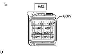
- Disconnect the H58 airbag ECU assembly connector.
- Connect the cable to the negative (-) auxiliary battery terminal.
Post-procedure1
- Measure the voltage according to the value(s) in the table below.
Standard Voltage
Tester Connection Condition Specified Condition H58-25 (GSW) - Body ground Ignition switch ON 4.3 to 5.5 V Result
Proceed to OK NG *a Front view of wire harness connector
(to Airbag ECU Assembly)Procedure1
- None
Result:
NG
See step 7
Result:
OK
See step 4
- Disconnect the cable from the negative (-) auxiliary battery terminal.
- REPLACE AIRBAG ECU ASSEMBLY
Pre-procedure1
- Disconnect the cable from the negative (-) auxiliary battery terminal.WARNING:
Wait at least 90 seconds after disconnecting the cable from the negative (-) auxiliary battery terminal to disable the SRS system.
Procedure1
- Replace the airbag ECU assembly.
HINT:
Refer to REMOVAL [11/2023 - ]
Result
Proceed to NEXT Post-procedure1
- None
Result:
NEXT
See step 5
- Disconnect the cable from the negative (-) auxiliary battery terminal.
- CLEAR DTC
Result:
NEXT
See step 6
- CHECK DTC OUTPUT
- Recheck for DTCs.
Body Electrical > Main Body > Trouble Codes
Result
Result Proceed to B1243-00 is not output A B1243-00 is output B
Result:
A
END (AIRBAG ECU ASSEMBLY WAS DEFECTIVE)
Result:
B
REPLACE MAIN BODY ECU (MULTIPLEX NETWORK BODY ECU). Refer to REMOVAL [11/2023 - ]
- Recheck for DTCs.
- CHECK HARNESS AND CONNECTOR (AIRBAG ECU ASSEMBLY - POWER DISTRIBUTION BOX ASSEMBLY)
Pre-procedure1
- Disconnect the cable from the negative (-) auxiliary battery terminal.WARNING:
Wait at least 90 seconds after disconnecting the cable from the negative (-) auxiliary battery terminal to disable the SRS system.
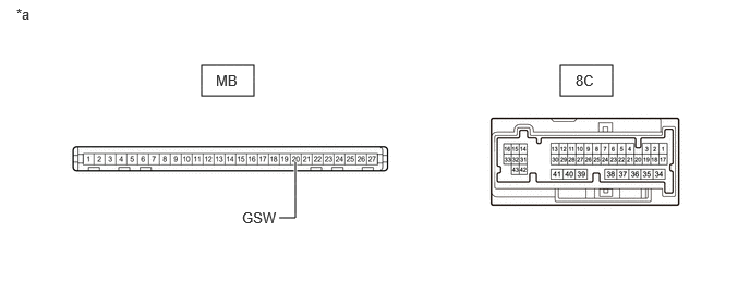
- Disconnect the 8C power distribution box assembly connector.
Procedure1
- Measure the resistance according to the value(s) in the table below.
Standard Resistance
Tester Connection Condition Specified Condition H58-25 (GSW) - 8C-43 Always Below 1 Ω H58-25 (GSW) or 8C-43 - Other terminals and body ground Always 10 kΩ or higher Result
Proceed to OK NG Post-procedure1
- None
Result:
NG
REPAIR OR REPLACE HARNESS OR CONNECTOR
Result:
OK
See step 8
- Disconnect the cable from the negative (-) auxiliary battery terminal.
- INSPECT POWER DISTRIBUTION BOX ASSEMBLY
Pre-procedure1
- Remove the power distribution box assembly.
HINT:
Refer to REMOVAL [11/2023 - ]
- Remove the main body ECU (multiplex network body ECU).
*a Component without harness connected
(Power Distribution Box Assembly)- - Procedure1
- Measure the resistance according to the value(s) in the table below.
Standard Resistance
Tester Connection Condition Specified Condition MB-20 (GSW) - 8C-43 Always Below 1 Ω Result
Proceed to OK NG Post-procedure1
- None
Result:
OK
REPLACE MAIN BODY ECU (MULTIPLEX NETWORK BODY ECU). Refer to REMOVAL [11/2023 - ]
Result:
NG
REPLACE POWER DISTRIBUTION BOX ASSEMBLY. Refer to REMOVAL [11/2023 - ]
- Remove the power distribution box assembly.