Installation [11/2023 - ]: Procedure
WARNING: This page is about a different variant/trim than selected.
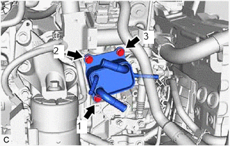
- INSTALL MOTOR COOLING COOLER
- CONNECT NO. 1 MOTOR COOLING HOSE
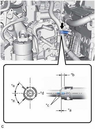
- Connect the No. 1 motor cooling hose to the motor cooling cooler, and slide the clip to secure it.
*a 0 to 3 mm (0 to 0.118 in.) *b 2 to 7 mm (0.0787 to 0.276 in.) *c Paint Mark *d Center of Paint Mark *e 45° (Claw of Clip Location) NOTE:- Be careful not to deform the motor cooling cooler.
- Make sure to align the paint mark of the No. 1 motor cooling hose with the paint mark of the motor cooling cooler.
- Make sure that the claws of the clip are within the location shown in the illustration.
- Connect the No. 1 motor cooling hose to the motor cooling cooler, and slide the clip to secure it.
- CONNECT OUTLET MOTOR HOSE
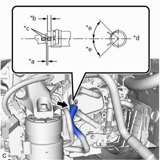
- Connect the outlet motor hose to the motor cooling cooler and slide the clip to secure it.NOTE:
- Make sure to slide the outlet motor hose until it contacts the hose stopper of the motor cooling cooler.
- Make sure to align the paint mark of the outlet motor hose with the paint mark of the motor cooling cooler.
- Make sure that the claws of the clip are within the location shown in the illustration.
*a 0 to 3 mm (0 to 0.118 in.) *b 2 to 7 mm (0.0787 to 0.276 in.) *c Paint Mark *d Center of Paint Mark *e 45° (Claw of Clip Location)
- Connect the outlet motor hose to the motor cooling cooler and slide the clip to secure it.
- CONNECT NO. 5 INVERTER COOLING HOSE
Refer to PROCEDURE - Step 30
- CONNECT NO. 1 INVERTER COOLING HOSE
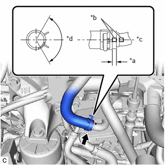
- Connect the No. 1 inverter cooling hose to the motor cooling cooler, and slide the clip to secure it.
*a 2 to 7 mm (0.0787 to 0.276 in.) *b Paint Mark *c Center of Paint Mark *d 120° (Claw of Clip Location) NOTE:- Be careful not to deform the motor cooling cooler.
- Make sure to align the paint mark of the No. 1 inverter cooling hose with the paint mark of the motor cooling cooler.
- Make sure that the claws of the clip are within the location shown in the illustration.
- Connect the No. 1 inverter cooling hose to the motor cooling cooler, and slide the clip to secure it.
- INSTALL AIR CLEANER ASSEMBLY WITH AIR CLEANER HOSE
Refer to PROCEDURE - Step 19
- INSTALL INLET AIR CLEANER ASSEMBLY
Refer to PROCEDURE - Step 20
- INSTALL COOL AIR INTAKE DUCT SEAL
Refer to PROCEDURE - Step 4
- INSTALL NO. 1 ENGINE COVER SUB-ASSEMBLY
Refer to PROCEDURE - Step 64
- INSPECT HYBRID TRANSAXLE FLUID
See step 5
- INSPECT FOR HYBRID TRANSAXLE FLUID LEAK
- ADD COOLANT (for Inverter)
Refer to PROCEDURE - Step 2
- INSPECT FOR COOLANT LEAK (for Inverter)
Refer to PROCEDURE - Step 1
- INSTALL NO. 2 ENGINE UNDER COVER ASSEMBLY
Refer to PROCEDURE - Step 60
- INSTALL NO. 1 ENGINE UNDER COVER
Refer to PROCEDURE - Step 61
- INSTALL FRONT WHEEL OPENING EXTENSION PAD RH
Refer to PROCEDURE - Step 63
- INSTALL FRONT WHEEL OPENING EXTENSION PAD LH
Refer to PROCEDURE - Step 62