Replacement [12/2019 - ]: Procedure
- DRAIN COOLANT (for Inverter) WARNING:
To avoid the danger of being burned, do not remove the reserve tank cap while the coolant (for inverter) is still hot. Pressurized, hot coolant (for inverter) and steam may be released and cause serious burns.
NOTE:- Do not reuse the drained coolant because it may contain foreign matter.
- Collect the drained coolant and measure its volume to establish a benchmark. When adding coolant, make sure to add more coolant than the measured amount.
- Remove the reserve tank cap from the inverter reserve tank assembly.
- Remove the front wheel opening extension pad LH.
Refer to PROCEDURE - Step 7 [12/2019 - 10/2022] , or refer to PROCEDURE - Step 7 [10/2022 - 11/2023] , or refer to PROCEDURE - Step 7 [11/2023 - ]
- Remove the front wheel opening extension pad RH.
Refer to PROCEDURE - Step 8 [12/2019 - 10/2022] , or refer to PROCEDURE - Step 8 [10/2022 - 11/2023] , or refer to PROCEDURE - Step 8 [11/2023 - ]
- Remove the No. 1 engine under cover assembly.
Refer to PROCEDURE - Step 9 [12/2019 - 10/2022] , or refer to PROCEDURE - Step 9 [10/2022 - 11/2023] , or refer to PROCEDURE - Step 9 [11/2023 - ]
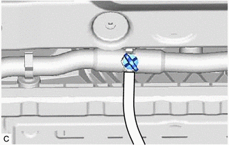
- Connect a hose with an inside diameter of 9 mm (0.354 in.) to the drain cock as shown in the illustration.
- Loosen the drain cock plug indicated in the illustration and drain the coolant.WARNING:
To avoid the danger of being burned, do not loosen the drain cock plug while the coolant (for inverter) is still hot. Pressurized, hot coolant (for inverter) and steam may be released and cause serious burns.
- Tighten the drain cock plug by hand.
- Disconnect the hose from the drain cock.
- Install the No. 1 engine under cover assembly.
Refer to PROCEDURE - Step 63 [12/2019 - 10/2022] , or refer to PROCEDURE - Step 63 [10/2022 - 11/2023] , or refer to PROCEDURE - Step 61 [11/2023 - ]
- Install the front wheel opening extension pad LH.
Refer to PROCEDURE - Step 64 [12/2019 - 10/2022] , or refer to PROCEDURE - Step 64 [10/2022 - 11/2023] , or refer to PROCEDURE - Step 62 [11/2023 - ]
- Install the front wheel opening extension pad RH.
Refer to PROCEDURE - Step 65 [12/2019 - 10/2022] , or refer to PROCEDURE - Step 65 [10/2022 - 11/2023] , or refer to PROCEDURE - Step 63 [11/2023 - ]
- ADD COOLANT (for Inverter) NOTE:
- Do not reuse the drained coolant because it may contain foreign matter.
- If the vehicle is driven with air in the inverter cooling system, damage may occur and the following DTCs may be stored.
DTC No. Detection Item P0A93-00 Inverter "A" Cooling System Performance P0A00-1C Motor Electronics Coolant Temperature Sensor Circuit Voltage Out of Range P0A78-9E Drive Motor "A" Inverter Stuck On P1C5D-19 Drive Motor "A" Inverter Circuit Current Above Threshold P0A7A-9E Generator Inverter Stuck On P1C5F-19 Generator Inverter Circuit Current Above Threshold P0A94-9E DC/DC Converter Stuck On P0D33-19 DC/DC Converter Circuit Current Above Threshold P0AED-1C Drive Motor Inverter Temperature Sensor "A" Circuit Voltage Out of Range P0C38-1C DC/DC Converter Temperature Sensor "A" Circuit Voltage Out of Range P0C3D-1C DC/DC Converter Temperature Sensor "B" Circuit Voltage Out of Range P1CCC-96 DC/DC Converter Enable Component Internal Failure
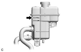
- Slowly pour coolant into the inverter reserve tank assembly until it reaches the FULL line.
Standard Capacity
1.9 liters (2.0 US qts, 1.7 Imp. qts)
NOTE:To prevent foreign matter such as dust or dirt from entering the cooling system, make sure to confirm that the container used to add coolant is clean and free of foreign matter.
- Activate the Inverter Water Pump
Powertrain > Hybrid Control > Active Test
Tester Display Activate the Inverter Water Pump HINT:
The inverter water pump with motor assembly can also be operated using inspection mode.
- While adding coolant to the inverter reserve tank assembly to keep the coolant at the FULL line and compensate for the drop in the coolant level as the air bleeds, operate and stop the inverter water pump with motor assembly at 1 minute intervals.
Standard
Air bleeding from the inverter cooling system is completed when the noise made by the inverter water pump with motor assembly becomes smaller and the circulation of coolant in the inverter reserve tank assembly improves.
HINT:
Loud noises made by the inverter water pump with motor assembly and poor circulation of coolant in the inverter reserve tank assembly indicate that there is air in the cooling system.
- After the air is completely bled from the cooling system, add coolant to the FULL line of inverter reserve tank assembly and install the reserve tank cap.NOTE:
Make sure that more coolant than the volume collected coolant volume is added.
- INSPECT FOR COOLANT LEAK (for Inverter)
Refer to PROCEDURE - Step 1