Installation [12/2019 - 10/2022]: Procedure
- INSTALL ENGINE MOUNTING INSULATOR SUB-ASSEMBLY LH
HINT:
Perform this procedure only when replacement of the engine mounting insulator sub-assembly LH is necessary.
- INSTALL ENGINE MOUNTING SPACER
HINT:
Perform this procedure only when replacement of the engine mounting spacer is necessary.
- INSTALL ENGINE MOUNTING INSULATOR SUB-ASSEMBLY RH
HINT:
Perform this procedure only when replacement of the engine mounting insulator sub-assembly RH is necessary.
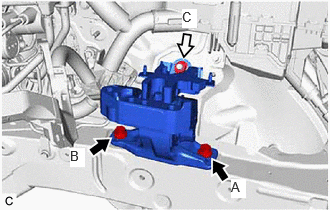
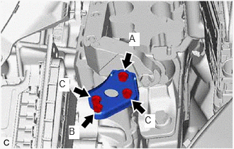
- Install the engine mounting insulator sub-assembly RH with the 2 bolts and nut.
Torque: 72 N*m (734 kgf*cm, 53 ft.*lbf)
NOTE:Temporarily tighten the bolt (A), and then fully tighten the 2 bolts and nut in the order of (B), (A) and (C).
- Connect the No. 2 earth wire to the engine mounting insulator sub-assembly RH with the bolt.
Torque: 10 N*m (102 kgf*cm, 7 ft.*lbf)
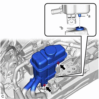
- Connect the radiator reserve tank assembly with the bolt and nut.
Torque: 5.0 N*m (51 kgf*cm, 44 in.*lbf)
- Engage the 2 clamps.
- Install the No. 1 inverter reserve tank bracket with the bolt.
Torque: 14 N*m (143 kgf*cm, 10 ft.*lbf)
- Install the engine mounting insulator sub-assembly RH with the 2 bolts and nut.
- CONNECT INVERTER RESERVE TANK ASSEMBLY
- INSTALL ENGINE HANGERS
Refer to PROCEDURE - Step 41
- REMOVE ENGINE ASSEMBLY FROM ENGINE STAND
- Remove the engine assembly from the engine stand.
- INSTALL NO. 1 CRANKSHAFT POSITION SENSOR PLATE
Refer to PROCEDURE - Step 2
- INSTALL FLYWHEEL SUB-ASSEMBLY
Refer to PROCEDURE - Step 3
- INSTALL TRANSMISSION INPUT DAMPER ASSEMBLY
Refer to PROCEDURE - Step 4
- INSTALL HYBRID VEHICLE TRANSAXLE ASSEMBLY
Refer to PROCEDURE - Step 12
- INSTALL REAR ENGINE MOUNTING INSULATOR
HINT:
Perform this procedure only when replacement of the rear engine mounting insulator is necessary.
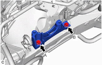
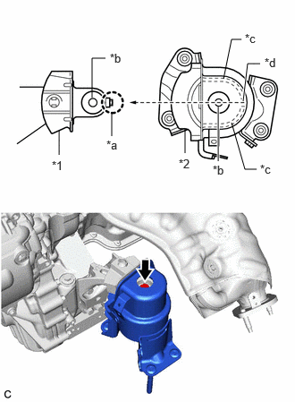
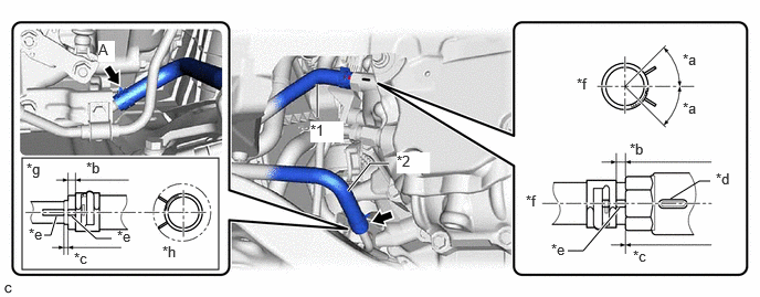
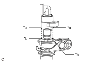
- Align and insert the protrusion of the rear engine mounting bracket into the gap between the 2 inner walls of the rear engine mounting insulator to align the hole of the rear engine mounting bracket with the bolt hole of the rear engine mounting insulator, and install the rear engine mounting insulator with the bolt.
Torque: 72 N*m (734 kgf*cm, 53 ft.*lbf)
*1 Rear Engine Mounting Bracket *2 Rear Engine Mounting Insulator *a Protrusion *b Hole *c Wall *d Gap - Install the wire harness clamp to the rear engine mounting insulator with the bolt.
Torque: 13 N*m (133 kgf*cm, 10 ft.*lbf)
- Align and insert the protrusion of the rear engine mounting bracket into the gap between the 2 inner walls of the rear engine mounting insulator to align the hole of the rear engine mounting bracket with the bolt hole of the rear engine mounting insulator, and install the rear engine mounting insulator with the bolt.
- INSTALL FRONT ENGINE MOUNTING INSULATOR
HINT:
Perform this procedure only when replacement of the front engine mounting insulator is necessary.
- Install the front engine mounting insulator to the front engine mounting bracket with the bolt.
Torque: 72 N*m (734 kgf*cm, 53 ft.*lbf)
- Install the front engine mounting insulator to the front engine mounting bracket with the bolt.
- INSTALL FRONT FRAME ASSEMBLY
Refer to PROCEDURE - Step 8
- INSTALL FLYWHEEL HOUSING SIDE COVER
Refer to PROCEDURE - Step 18
- INSTALL OIL PUMP WITH MOTOR ASSEMBLY
Refer to PROCEDURE - Step 1
- CONNECT NO. 2 TRANSMISSION OIL COOLER HOSE ASSEMBLY
Refer to PROCEDURE - Step 2
- INSTALL HEATER WATER HOSE
- Install the heater water hose to the flow shutting valve (water by-pass hose assembly) and slide the clip to secure it.
- Engage the clamp to connect the heater water hose.
- INSTALL HV AIR CONDITIONING WIRE
- Engage the guide to install the HV air conditioning wire to the hybrid vehicle transaxle assembly.
- Install the 2 bolts.
Torque: 20 N*m (204 kgf*cm, 15 ft.*lbf)
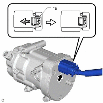
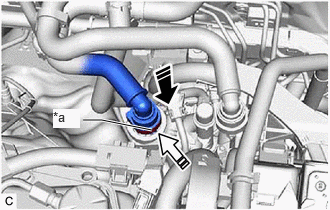
- Connect the connector and slide the green-colored lock as shown in the illustration to lock it securely.WARNING:
Make sure to wear insulated gloves.
NOTE:Make sure that the connector is connected securely.
*a Green-colored Lock 
Slide - Engage the 2 clamps.
- INSTALL ENGINE WIRE
- Connect all connectors and clamps, and install the engine wire to the engine assembly with transaxle.
- INSTALL STEERING GEAR HEAT INSULATOR
Refer to PROCEDURE - Step 8
- INSTALL FLYWHEEL HOUSING UNDER COVER
- Install the flywheel housing under cover to the cylinder block sub-assembly.
- INSTALL ENGINE ASSEMBLY WITH TRANSAXLE
HINT:
Perform "Inspection After Repair" after replacing the engine assembly.
Refer to INITIALIZATION [12/2019 - 10/2021] , or refer to INITIALIZATION [10/2021 - ]
- Set the engine assembly with transaxle on an engine lifter.NOTE:
- Using height adjustment attachments and plate lift attachments, keep the engine assembly with transaxle level.
- Do not perform any procedures while the engine assembly is suspended because doing so may cause the engine assembly to drop, resulting in injury. However, the engine assembly needs to be suspended when it is installed to or removed from an engine stand.
- Remove the 4 bolts, No. 1 engine hanger and No. 2 engine hanger from the cylinder head sub-assembly and engine mounting bracket RH.
- Install the fuel delivery guard to the engine mounting bracket RH with the bolt.
Torque: 40 N*m (408 kgf*cm, 30 ft.*lbf)
- Operate the engine lifter and install the engine assembly with transaxle to the vehicle.WARNING:
Do not raise the engine assembly with transaxle more than necessary. If the engine is raised excessively, the vehicle may also be lifted up.
NOTE:- Make sure that the engine assembly with transaxle is clear of all wiring and hoses.
- While raising the engine assembly with transaxle into the vehicle, do not allow it to contact the vehicle.
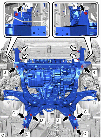
- Install the front bumper extension sub-assembly RH and front bumper extension sub-assembly LH to the front frame assembly and vehicle body with the 4 bolts and 4 nuts.

Bolt 
Nut Bolt (A)
Torque: 9.5 N*m (97 kgf*cm, 84 in.*lbf)
Bolt (B)
Torque: 135 N*m (1377 kgf*cm, 100 ft.*lbf)
Nut
Torque: 12.5 N*m (127 kgf*cm, 9 ft.*lbf)
- Install the front suspension member brace rear RH and front suspension member brace rear LH to the front frame assembly and vehicle body with the 6 bolts.
Bolt (C)
Torque: 60 N*m (612 kgf*cm, 44 ft.*lbf)
Bolt (D)
Torque: 135 N*m (1377 kgf*cm, 100 ft.*lbf)
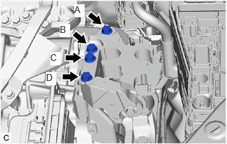
- Install the engine mounting insulator sub-assembly LH to the hybrid vehicle transaxle assembly with the 4 bolts.
Torque: 42 N*m (428 kgf*cm, 31 ft.*lbf)
NOTE:Fully tighten the 4 bolts in the order of (A), (C), (B) and (D).
- Install the engine mounting stay LH to the engine mounting insulator sub-assembly LH with the 4 bolts.
Torque: 8.0 N*m (82 kgf*cm, 71 in.*lbf)
NOTE:Temporarily tighten the bolt (A), and then fully tighten the 4 bolts in the order of (B), (C) and (A).
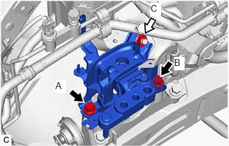
- Install the engine mounting insulator sub-assembly RH to the engine mounting bracket RH with the 3 bolts and nut.
Bolt
Torque: 72 N*m (734 kgf*cm, 53 ft.*lbf)
Nut
Torque: 42 N*m (428 kgf*cm, 31 ft.*lbf)
- Set the engine assembly with transaxle on an engine lifter.
- CONNECT HEATER WATER HOSE
- Connect the heater water hose to the No. 1 air conditioning accessory assembly and slide the clip to secure it.
- INSTALL FRONT DRIVE SHAFT ASSEMBLY
Refer to INSTALLATION [12/2019 - ]
- INSTALL FRONT EXHAUST PIPE ASSEMBLY (TWC: Rear Catalyst)
Refer to PROCEDURE - Step 7
- INSTALL FRONT FLOOR COVER LH
- Engage the 5 clamps to install the front floor cover LH to the vehicle body with the 5 bolts, 3 screws, 2 clips (A) and clip (B).
Bolt
Torque: 7.5 N*m (76 kgf*cm, 66 in.*lbf)
- Engage the 5 clamps to install the front floor cover LH to the vehicle body with the 5 bolts, 3 screws, 2 clips (A) and clip (B).
- INSTALL FRONT FLOOR COVER RH
- Engage the 4 clamps to install the front floor cover RH to the vehicle body with the 3 bolts, 3 screws and clip.
Bolt
Torque: 7.5 N*m (76 kgf*cm, 66 in.*lbf)
- Engage the 4 clamps to install the front floor cover RH to the vehicle body with the 3 bolts, 3 screws and clip.
- CONNECT STEERING INTERMEDIATE SHAFT ASSEMBLY
Refer to PROCEDURE - Step 12
- CONNECT NO. 4 WATER BY-PASS HOSE
- CONNECT WIRE HARNESS
- Connect the earth wire with the 2 bolts.
Torque: 10 N*m (102 kgf*cm, 7 ft.*lbf)
- Engage the claw to connect the wire harness to the No. 1 engine room relay block and No. 1 junction block assembly.
- Connect the 4 connectors to the No. 1 engine room relay block and No. 1 junction block assembly.
- Install the nut to the No. 1 engine room relay block and No. 1 junction block assembly.
Torque: 8.0 N*m (82 kgf*cm, 71 in.*lbf)
- Engage the 3 claws and install the No. 1 relay block cover to the No. 1 engine room relay block and No. 1 junction block assembly.
- Connect the earth wire with the 2 bolts.
- CONNECT NO. 1 TRANSMISSION OIL COOLER HOSE ASSEMBLY
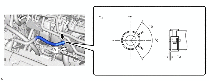
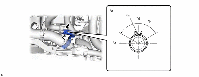
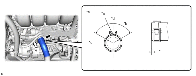
- Connect the outlet motor hose to the hybrid vehicle transaxle assembly and slide the clip to secure it.
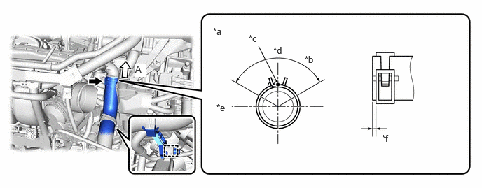
*1 Inlet Motor Hose *2 Outlet Motor Hose *a 45° (Claw of Clip Location) *b 2 to 7 mm (0.0787 to 0.276 in.) *c 0 to 3 mm (0 to 0.118 in.) *d Marking *e Paint Mark *f Center of Paint Mark *g View A *h 360° (Claw of Clip Location) - Connect the inlet motor hose to the hybrid vehicle transaxle assembly and slide the clip to secure it.
- Engage the clamp.
- Connect the outlet motor hose to the hybrid vehicle transaxle assembly and slide the clip to secure it.
- CONNECT NO. 5 INVERTER COOLING HOSE
- CONNECT SUCTION HOSE SUB-ASSEMBLY
Refer to PROCEDURE - Step 3
- CONNECT DISCHARGE HOSE SUB-ASSEMBLY
- Remove the vinyl tape from the discharge hose sub-assembly.
- Sufficiently apply compressor oil to a new O-ring and the fitting surface of the compressor with motor assembly.
Compressor Oil
ND-OIL 11 or equivalent
- Install the O-ring to the discharge hose sub-assembly.NOTE:
- Keep the O-ring and O-ring fitting surface free of foreign matter.
- Do not use any compressor oil other than ND-OIL 11 or equivalent. If any compressor oil other than ND-OIL 11 or equivalent is used, compressor motor insulation performance may decrease, resulting in leakage of electric power.
- Connect the discharge hose sub-assembly to the compressor with motor assembly with the bolt.
Torque: 9.8 N*m (100 kgf*cm, 87 in.*lbf)
- CONNECT NO. 2 RADIATOR HOSE
- CONNECT NO. 1 RADIATOR HOSE
- CONNECT FUEL TUBE SUB-ASSEMBLY
- Connect the fuel tube sub-assembly.
- Connect the fuel tube sub-assembly to the fuel pipe.
Refer to PRECAUTION [12/2019 - 11/2023]
- Connect the fuel tube sub-assembly to the fuel pipe.
- Install the No. 1 fuel pipe clamp to the fuel tube connector.
- Connect the fuel tube sub-assembly.
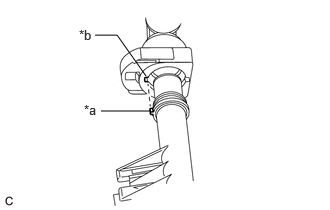
- CONNECT INLET HEATER WATER HOSE B
- Align the protrusions of the inlet heater water hose B connector with the cutouts in the flow shutting valve (water by-pass hose assembly) and securely insert the inlet heater water hose B connector into the stopper of the pipe.
*a Protrusion *b Cutout - Push in the retainer.
*a Retainer 
Push 
Push in - Check that the flow shutting valve (water by-pass hose assembly) and inlet heater water hose B connector are securely connected by pulling on them.
- Align the protrusions of the inlet heater water hose B connector with the cutouts in the flow shutting valve (water by-pass hose assembly) and securely insert the inlet heater water hose B connector into the stopper of the pipe.
- CONNECT OUTLET HEATER WATER HOSE B
- Align the protrusion of the No. 2 water by-pass pipe sub-assembly with the cutout in the outlet heater water hose B connector and securely insert the outlet heater water hose B connector into the stopper of the pipe.
*a Protrusion *b Cutout - Push in the retainer.
*a Retainer Push Push in - Check that the No. 2 water by-pass pipe sub-assembly and outlet heater water hose B connector are securely connected by pulling on them.
- Align the protrusion of the No. 2 water by-pass pipe sub-assembly with the cutout in the outlet heater water hose B connector and securely insert the outlet heater water hose B connector into the stopper of the pipe.
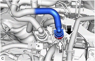
- CONNECT FUEL VAPOR FEED HOSE ASSEMBLY
- Connect the fuel vapor feed hose assembly to the No. 1 vacuum switching valve assembly and slide the clip to secure it.
- Engage the clamp.
- INSTALL INVERTER WITH CONVERTER ASSEMBLY
Refer to INSTALLATION [12/2019 - 11/2023]
- INSTALL NO. 2 FRONT BUMPER REINFORCEMENT
Refer to PROCEDURE - Step 3
- INSTALL FRONT BUMPER LOWER ABSORBER
Refer to PROCEDURE - Step 5
- INSTALL HEADLIGHT ASSEMBLY LH
Refer to INSTALLATION [12/2019 - 09/2020] , or refer to INSTALLATION [09/2020 - ]
- ADD ENGINE OIL
Refer to PROCEDURE - Step 5 [12/2019 - 10/2021] , or refer to PROCEDURE - Step 5 [10/2021 - 10/2022]
- ADD HYBRID TRANSAXLE FLUID
Refer to PROCEDURE - Step 6
- ADD ENGINE COOLANT (for Engine)
Refer to PROCEDURE - Step 2
- CHARGE AIR CONDITIONING SYSTEM WITH REFRIGERANT
Refer to PROCEDURE - Step 2
- WARM UP COMPRESSOR
Refer to PROCEDURE - Step 4
- INSPECT SHIFT LEVER POSITION
Refer to PROCEDURE - Step 2
- ADJUST SHIFT LEVER POSITION
Refer to ADJUSTMENT [12/2019 - ]
- INSPECT FOR ENGINE OIL LEAK
Refer to PROCEDURE - Step 6 [12/2019 - 10/2021] , or refer to PROCEDURE - Step 6 [10/2021 - 10/2022]
- INSPECT FOR COOLANT LEAK (for Engine)
Refer to PROCEDURE - Step 1
- INSPECT FOR REFRIGERANT LEAK
Refer to PROCEDURE - Step 5
- INSPECT FOR FUEL LEAK
Refer to PROCEDURE - Step 1
- INSPECT FOR EXHAUST GAS LEAK
Refer to PROCEDURE - Step 6
- CHECK ENGINE OIL LEVEL
Refer to PROCEDURE - Step 1
- INSPECT HYBRID TRANSAXLE FLUID
Refer to PROCEDURE - Step 5
- INSPECT ENGINE COOLANT LEVEL IN RESERVOIR TANK
Refer to PROCEDURE - Step 2
- INSTALL FRONT FENDER APRON SEAL LH
- Install the front fender apron seal LH with the 2 bolts and clip.
Torque: 7.5 N*m (76 kgf*cm, 66 in.*lbf)
- Install the front fender apron seal LH with the 2 bolts and clip.
- INSTALL FRONT FENDER APRON SEAL RH
- Install the front fender apron seal RH with the 2 bolts and clip.
Torque: 7.5 N*m (76 kgf*cm, 66 in.*lbf)
- Install the front fender apron seal RH with the 2 bolts and clip.
- INSTALL NO. 2 ENGINE UNDER COVER ASSEMBLY
- Install the No. 2 engine under cover assembly with the 2 bolts, 2 screws and 6 clips.
Bolt
Torque: 7.5 N*m (76 kgf*cm, 66 in.*lbf)
- Install the No. 2 engine under cover assembly with the 2 bolts, 2 screws and 6 clips.
- INSTALL NO. 1 ENGINE UNDER COVER
- Install the No. 1 engine under cover with the 3 bolts, 8 screws and 2 clips.
Bolt
Torque: 7.5 N*m (76 kgf*cm, 66 in.*lbf)
- Install the No. 1 engine under cover with the 3 bolts, 8 screws and 2 clips.
- INSTALL FRONT WHEEL OPENING EXTENSION PAD LH
- Install the front wheel opening extension pad LH with the 4 screws.
- INSTALL FRONT WHEEL OPENING EXTENSION PAD RH
- Install the front wheel opening extension pad RH with the 4 screws.
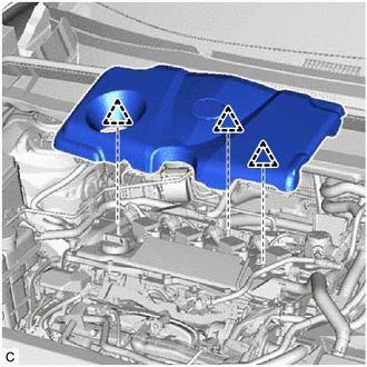
- INSTALL NO. 1 ENGINE COVER SUB-ASSEMBLY
- INSTALL FRONT WHEELS
Refer to INSTALLATION [12/2019 - 10/2022]
- ALIGN FRONT WHEELS FACING STRAIGHT AHEAD
- INSPECT AND ADJUST FRONT WHEEL ALIGNMENT
Refer to ADJUSTMENT [12/2019 - 09/2020] , or refer to ADJUSTMENT [09/2020 - 10/2022]
- PERFORM INITIALIZATION
Refer to PROCEDURE - Step 9 [12/2019 - 09/2020] , or refer to PROCEDURE - Step 9 [09/2020 - ]
- INSPECT IGNITION TIMING
Refer to PROCEDURE - Step 7
- INSPECT ENGINE IDLE SPEED
Refer to PROCEDURE - Step 8
- INSPECT CO/HC
Refer to PROCEDURE - Step 10
- CHECK SPEED SENSOR SIGNAL