Installation [12/2019 - 10/2022]: Procedure
- INSTALL HOLE PLUG (w/ HOLE PLUG)
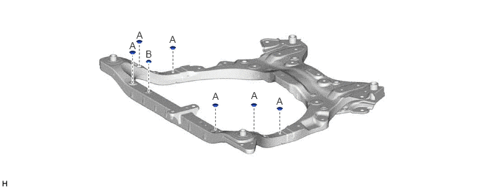
- INSTALL OIL COOLER BRACKET
- Install the oil cooler bracket to the front frame assembly with the bolt.
Torque: 19.5 N.m (199 kgf/cm, 14 ft.lbf)
- Install the oil cooler bracket to the front frame assembly with the bolt.
- INSTALL NO. 2 EXHAUST PIPE SUPPORT BRACKET (for A25A-FXS)
- Install the No. 2 exhaust pipe support bracket to the front frame assembly with the 2 bolts.
Torque: 29 N.m (296 kgf/cm, 21 ft.lbf)
- Install the No. 2 exhaust pipe support bracket to the front frame assembly with the 2 bolts.
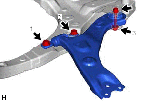
- INSTALL FRONT LOWER NO. 1 SUSPENSION ARM SUB-ASSEMBLY LH
- Install the front lower arm bushing stopper to the front lower No. 1 suspension arm sub-assembly LH.
- Install the front lower No. 1 suspension arm sub-assembly LH to the front frame assembly with the 3 bolts and nut in the order shown in the illustration.
 Courtesy of © TOYOTA, LICENSE AGREEMENT TMS1002
Bolt (1), (2)
Torque: 200 N.m (2039 kgf/cm, 148 ft.lbf)
Bolt (3)
Torque: 135 N.m (1377 kgf/cm, 100 ft.lbf)
NOTE:Because the nut has its own stopper, do not turn the nut. Tighten the bolt with the nut secured.
- INSTALL FRONT LOWER NO. 1 SUSPENSION ARM SUB-ASSEMBLY RH
HINT:
Perform the same procedure as for the LH side.
- INSTALL RACK AND PINION POWER STEERING GEAR ASSEMBLY
Refer to PROCEDURE - Step 3
- INSTALL FRONT STABILIZER BAR SUB-ASSEMBLY WITH LINK
Refer to PROCEDURE - Step 4
- INSTALL FRONT FRAME ASSEMBLY
- Install the rear engine mounting insulator to the front frame assembly with the 4 nuts.
Torque: 72 N.m (734 kgf/cm, 53 ft.lbf)
- Install the front engine mounting insulator to the front frame assembly with the 3 nuts.
Torque: 72 N.m (734 kgf/cm, 53 ft.lbf)
- Install the rear engine mounting insulator to the front frame assembly with the 4 nuts.
- REMOVE ENGINE HANGERS (for 2GR-FKS)
Refer to PROCEDURE - Step 70 [12/2019 - 09/2020] , or refer to PROCEDURE - Step 70 [09/2020 - 10/2022]
- CONNECT WIRE HARNESS
Refer to PROCEDURE - Step 7
- INSTALL STEERING GEAR HEAT INSULATOR
Refer to PROCEDURE - Step 8
- INSTALL ENGINE ASSEMBLY WITH TRANSAXLE
for A25A-FXS: Refer to PROCEDURE - Step 22
for 2GR-FKS: Refer to PROCEDURE - Step 22 [12/2019 - 09/2020] , or refer to PROCEDURE - Step 22 [09/2020 - 10/2022]