Installation [12/2019 - 09/2020]: Procedure
- INSTALL ENGINE MOUNTING INSULATOR LH
HINT:
Perform this procedure only when replacement of the engine mounting insulator LH is necessary.
- for 2WD
Refer to PROCEDURE - Step 8
- for AWD
Refer to PROCEDURE - Step 10
- for 2WD
- INSTALL ENGINE MOUNTING BRACKET SUB-ASSEMBLY LH
HINT:
Perform this procedure only when replacement of the engine mounting bracket sub-assembly LH is necessary.
- INSTALL ENGINE MOUNTING SPACER
HINT:
Perform this procedure only when replacement of the engine mounting spacer is necessary.
- INSTALL ENGINE MOUNTING INSULATOR SUB-ASSEMBLY RH
HINT:
Perform this procedure only when replacement of the engine mounting insulator sub-assembly RH is necessary.
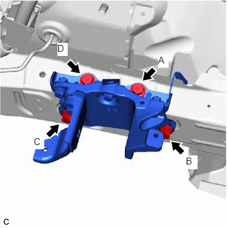
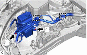
- Install the engine mounting insulator sub-assembly RH to the engine mounting spacer and vehicle body with the nut and 2 bolts.
Torque: 72 N.m (734 kgf/cm, 53 ft.lbf)
NOTE:Temporarily tighten the bolt (A), and then fully tighten the 2 bolts and nut in the order of (B), (A) and (C).
- Connect the No. 2 earth wire to the engine mounting insulator sub-assembly RH with the bolt.
Torque: 10 N.m (102 kgf/cm, 7 ft.lbf)
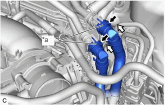
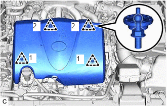
- Install the radiator reserve tank assembly with the bolt and nut in the order shown in the illustration.
 Courtesy of © TOYOTA, LICENSE AGREEMENT TMS1002
Torque: 5.0 N.m (51 kgf/cm, 44 in.lbf)
- Engage the 2 clamps.
- Install the engine mounting insulator sub-assembly RH to the engine mounting spacer and vehicle body with the nut and 2 bolts.
- INSTALL ENGINE HANGERS
See step 61
- REMOVE ENGINE ASSEMBLY FROM ENGINE STAND
- Remove the engine assembly from the engine stand.
- INSTALL NO. 1 CRANKSHAFT POSITION SENSOR PLATE
See step 2
- INSTALL DRIVE PLATE AND RING GEAR SUB-ASSEMBLY
See step 3
- INSTALL AUTOMATIC TRANSAXLE ASSEMBLY
- for 2WD
Refer to PROCEDURE - Step 14
- for AWD
Refer to PROCEDURE - Step 16
- for 2WD
- INSTALL FRONT ENGINE MOUNTING BRACKET
- for 2WD
Refer to PROCEDURE - Step 9
- for AWD
Refer to PROCEDURE - Step 11
- for 2WD
- INSTALL REAR ENGINE MOUNTING INSULATOR
HINT:
Perform this procedure only when replacement of the rear engine mounting insulator is necessary.
- Install the rear engine mounting insulator to the front frame assembly with the 4 nuts.
Torque: 72 N.m (734 kgf/cm, 53 ft.lbf)
- Install the rear engine mounting insulator to the front frame assembly with the 4 nuts.
- INSTALL FRONT ENGINE MOUNTING INSULATOR
HINT:
Perform this procedure only when replacement of the front engine mounting insulator is necessary.
- Install the front engine mounting insulator to the front frame assembly with the 3 nuts.
Torque: 72 N.m (734 kgf/cm, 53 ft.lbf)
- Install the front engine mounting insulator to the front frame assembly with the 3 nuts.
- INSTALL FRONT FRAME ASSEMBLY
- Install the rear engine mounting insulator to the rear engine mounting bracket sub-assembly with the bolt.
Torque: 72 N.m (734 kgf/cm, 53 ft.lbf)
- Install the front engine mounting insulator to the front engine mounting bracket with the bolt.
Torque: 72 N.m (734 kgf/cm, 53 ft.lbf)
- Install the rear engine mounting insulator to the rear engine mounting bracket sub-assembly with the bolt.
- REMOVE ENGINE HANGERS
See step 70
- INSTALL ENGINE WIRE
- Connect all connectors and clamps, and install the engine wire to the engine assembly with transaxle.
- CONNECT HOSE CLAMP
- for 2WD
Refer to PROCEDURE - Step 18
- for AWD
Refer to PROCEDURE - Step 20
- for 2WD
- CONNECT WATER BY-PASS HOSE ASSEMBLY
- for 2WD
Refer to PROCEDURE - Step 6
- for AWD
Refer to PROCEDURE - Step 6
- for 2WD
- INSTALL TRANSMISSION BREATHER CLAMP
- for 2WD
Refer to PROCEDURE - Step 7
- for AWD
Refer to PROCEDURE - Step 7
- for 2WD
- INSTALL BREATHER PLUG HOSE
- for 2WD
Refer to PROCEDURE - Step 21
- for AWD
Refer to PROCEDURE - Step 4
- for 2WD
- INSTALL STARTER ASSEMBLY
- w/ Stop And Start System
Refer to PROCEDURE - Step 1
- w/o Stop And Start System
Refer to PROCEDURE - Step 1
- w/ Stop And Start System
- CONNECT VACUUM HOSE
- for 2WD
Refer to PROCEDURE - Step 22
- for AWD
Refer to PROCEDURE - Step 24
- for 2WD
- INSTALL ENGINE ASSEMBLY WITH TRANSAXLE
HINT:
Perform Inspection After Repair after replacing the engine assembly.
Refer to INITIALIZATION [12/2019 - 10/2022]
- Using height adjustment attachments and plate lift attachments to keep the engine assembly with transaxle and front frame assembly level, set an engine lifter underneath the engine assembly with transaxle and front frame assembly.NOTE:
- Do not perform any procedures while the engine assembly is suspended because doing so may cause the engine assembly to drop, resulting in injury. However, the engine assembly needs to be suspended when it is installed to or removed from an engine stand.
- To prevent the engine assembly from unexpectedly moving, securely support the engine assembly until it is secured to an engine stand.
- Operate the engine lifter and install the engine assembly with transaxle to the vehicle.WARNING:
Do not raise the engine assembly with transaxle more than necessary. If the engine is raised excessively, the vehicle may also be lifted up.
NOTE:- Make sure that the engine assembly with transaxle is clear of all wiring and hoses.
- While raising the engine assembly with transaxle into the vehicle, do not allow it to contact the vehicle.
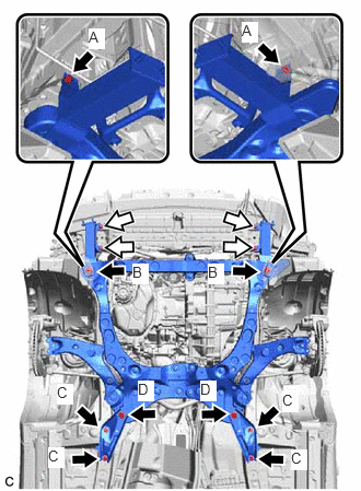
- Install the front bumper extension sub-assembly RH and front bumper extension sub-assembly LH to the front frame assembly and vehicle body with the 4 bolts and 4 nuts.

Bolt 
Nut Bolt (A)
Torque: 9.5 N.m (97 kgf/cm, 84 in.lbf)
Bolt (B)
Torque: 135 N.m (1377 kgf/cm, 100 ft.lbf)
Nut
Torque: 12.5 N.m (127 kgf/cm, 9 ft.lbf)
- Install the front suspension member brace rear RH and front suspension member brace rear LH to the front frame assembly and vehicle body with the 6 bolts.
Bolt (C)
Torque: 60 N.m (612 kgf/cm, 44 ft.lbf)
Bolt (D)
Torque: 135 N.m (1377 kgf/cm, 100 ft.lbf)
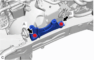
- Install the engine mounting insulator LH to the engine mounting bracket sub-assembly LH with the bolt and nut.
Torque: 42 N.m (428 kgf/cm, 31 ft.lbf)
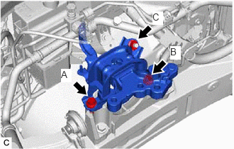
- Install the engine mounting insulator sub-assembly RH to the front No. 1 engine mounting bracket LH with the 3 bolts and nut.
Bolt
Torque: 72 N.m (734 kgf/cm, 53 ft.lbf)
Nut
Torque: 42 N.m (428 kgf/cm, 31 ft.lbf)
- Install the No. 2 engine mounting stay RH with the bolt and 2 nuts.
Torque: 20 N.m (204 kgf/cm, 15 ft.lbf)
- Using height adjustment attachments and plate lift attachments to keep the engine assembly with transaxle and front frame assembly level, set an engine lifter underneath the engine assembly with transaxle and front frame assembly.
- INSTALL NO. 2 FRONT BUMPER REINFORCEMENT
Refer to PROCEDURE - Step 3
- INSTALL FRONT BUMPER LOWER ABSORBER
Refer to PROCEDURE - Step 5
- INSTALL DRIVE PLATE AND TORQUE CONVERTER ASSEMBLY SETTING BOLT (for 2WD)
Refer to PROCEDURE - Step 28
- INSTALL DRIVE PLATE AND TORQUE CONVERTER ASSEMBLY SETTING BOLT (for AWD)
Refer to PROCEDURE - Step 30
- INSTALL FLYWHEEL HOUSING UNDER COVER
- Install the flywheel housing under cover with the 2 bolts.
Torque: 10 N.m (102 kgf/cm, 7 ft.lbf)
- Install the flywheel housing under cover with the 2 bolts.
- INSTALL FRONT DRIVE SHAFT ASSEMBLY
Refer to INSTALLATION [12/2019 - 10/2022]
- INSTALL EXHAUST MANIFOLD
Refer to INSTALLATION [12/2019 - 10/2022]
- INSTALL PROPELLER WITH CENTER BEARING SHAFT ASSEMBLY (for AWD)
Refer to INSTALLATION [12/2019 - 10/2022]
- CONNECT STEERING INTERMEDIATE SHAFT ASSEMBLY
Refer to PROCEDURE - Step 12
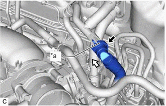
- CONNECT OUTLET NO. 1 OIL COOLER HOSE
- Connect the outlet No. 1 oil cooler hose to the oil cooler union sub-assembly and slide the clip to secure it.
- CONNECT NO. 3 TRANSMISSION OIL COOLER HOSE
- Engage the clamp.
- Connect the No. 3 transmission oil cooler hose to the No. 1 oil cooler tube sub-assembly without hose and slide the clip to secure it.
- CONNECT ENGINE WIRE
- Engage the 3 clamps.
- Engage the 2 clamps and connect the engine wire to the vehicle body.
- Connect the engine wire with the bolt.
Torque: 8.0 N.m (82 kgf/cm, 71 in.lbf)
- Engage the 2 clamps.
- Engage the claw and connect the engine wire to the engine room relay block and junction block assembly.
- Install the nut to the engine room relay block and junction block assembly.
Torque: 8.0 N.m (82 kgf/cm, 71 in.lbf)
- Connect the 5 connectors to the engine room relay block and junction block assembly.
- Install the No. 1 relay block cover to the engine room relay block and junction block assembly.
- CONNECT SUCTION HOSE SUB-ASSEMBLY
Refer to PROCEDURE - Step 3
- CONNECT DISCHARGE HOSE SUB-ASSEMBLY
Refer to PROCEDURE - Step 4
- CONNECT NO. 1 FUEL HOSE
- Connect the No. 1 fuel hose (for Port Injection).
- Connect the No. 1 fuel hose to the fuel pipe.
Refer to PRECAUTION [12/2019 - 10/2022]
- Connect the No. 1 fuel hose to the fuel pipe.
- Connect the No. 1 fuel hose (for Direct Injection).
- Connect the No. 1 fuel hose to the fuel pipe.
Refer to PRECAUTION [12/2019 - 10/2022]
- Connect the No. 1 fuel hose to the fuel pipe.
- Install the No. 1 fuel pipe clamp to the fuel tube connector.
- Engage the 2 claws to install the No. 2 fuel pipe clamp.
- Connect the No. 1 fuel hose (for Port Injection).
- CONNECT WATER BY-PASS HOSE ASSEMBLY
- w/ Heater Water Pump
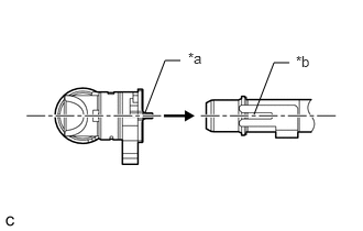
- Align the protrusion of the water by-pass hose assembly connector with the cutout in the heater water pump assembly and securely insert the water by-pass hose assembly connector to the stopper of the pipe.
*a Protrusion *b Cutout - Push in the retainer.
*a Retainer Push in Push - Check that the heater water pump assembly and water by-pass hose assembly connector are securely connected by pulling on them.
- Align the protrusion of the water by-pass hose assembly connector with the cutout in the heater water pump assembly and securely insert the water by-pass hose assembly connector to the stopper of the pipe.
- w/o Heater Water Pump
- Align the protrusion of the water by-pass hose assembly connector with the cutout in the water hose sub-assembly and securely insert the water by-pass hose assembly connector to the stopper of the pipe.
*a Protrusion *b Cutout - Push in the retainer.
*a Retainer Push in Push - Check that the water hose sub-assembly and water by-pass hose assembly connector are securely connected by pulling on them.
- Align the protrusion of the water by-pass hose assembly connector with the cutout in the water hose sub-assembly and securely insert the water by-pass hose assembly connector to the stopper of the pipe.
- w/ Heater Water Pump
- CONNECT INLET HEATER WATER HOSE B
- Connect the inlet heater water hose B to the water outlet and slide the clip to secure it.
- Engage the 2 clamps.
- CONNECT RADIATOR HOSE SUB-ASSEMBLY
- Connect the radiator hose sub-assembly to the water outlet and slide the clip to secure it.
- Connect the No. 4 water by-pass hose to the radiator hose sub-assembly and slide the clip to secure it.
- Install the radiator hose sub-assembly to the engine assembly with the 2 bolts.
Torque: 8.0 N.m (82 kgf/cm, 71 in.lbf)
- Engage the clamp.
- CONNECT NO. 2 RADIATOR HOSE
- Connect the No. 2 radiator hose to the water inlet and slide the clip to secure it.
- CONNECT CONNECTOR TO CHECK VALVE HOSE
- Connect the connector to check valve hose to the brake booster assembly and slide the clip to secure it.
- CONNECT NO. 1 FUEL VAPOR FEED HOSE
- Connect the No. 1 fuel vapor feed hose to the purge valve (purge VSV) and slide the clip to secure it.
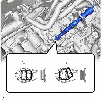
- CONNECT TRANSMISSION CONTROL CABLE ASSEMBLY
- Connect the transmission control cable assembly to the No. 1 transmission control cable bracket with a new clip.
- Connect the transmission control cable assembly to the transmission control shaft lever as shown in the illustration.
*a Correct *b Incorrect NOTE:Before installing the transmission control cable assembly, check that the park/neutral position switch assembly and shift lever are in N.
- INSTALL BATTERY CLAMP SUB-ASSEMBLY
- Install the battery clamp sub-assembly with the 3 bolts.
Torque: 18.5 N.m (189 kgf/cm, 14 ft.lbf)
- Engage the 5 clamps to the battery clamp sub-assembly.
- Install the battery clamp sub-assembly with the 3 bolts.
- INSTALL BATTERY
Refer to PROCEDURE - Step 1
- CONNECT ENGINE WIRE
- Connect the engine wire to the negative (-) battery terminal with the nut.
Torque: 7.6 N.m (77 kgf/cm, 67 in.lbf)
- Connect the engine wire to the negative (-) battery terminal with the nut.
- CONNECT ENGINE ROOM MAIN WIRE
- Connect the engine wire with engine room main wire to the positive (+) battery terminal with the nut.
Torque: 7.6 N.m (77 kgf/cm, 67 in.lbf)
- Connect the engine wire with engine room main wire to the positive (+) battery terminal with the nut.
- INSTALL ECM
Refer to PROCEDURE - Step 3
- INSTALL AIR CLEANER ASSEMBLY WITH AIR CLEANER HOSE
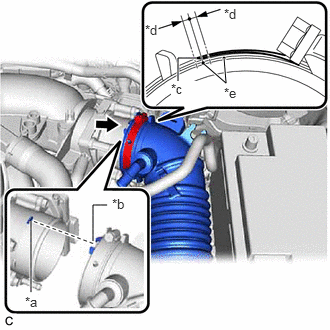
- Install the air cleaner assembly with air cleaner hose to the throttle body with motor assembly.NOTE:
Align the cutout of the air cleaner hose assembly with the protrusion of the throttle body with motor assembly.
*a Protrusion *b Cutout *c Hose Clamp End *d 2.0 mm (0.0787 in.) *e Paint Mark - Tighten the hose clamp in the position shown in the illustration.NOTE:
Make sure that the end of the hose clamp is positioned as shown in the illustration.
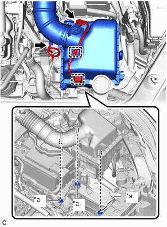
- Insert the 3 pins of the air cleaner assembly into the 3 air cleaner supports as shown in the illustration.
*a Air Cleaner Support NOTE:- Insert the 3 pins of the air cleaner assembly into the 3 air cleaner supports at the same time.
- Check that the pins are securely inserted into air cleaner supports.
- Engage the vacuum hose to the air cleaner hose.
- Engage the 2 wire harness clamps.
- Connect the mass air flow meter sub-assembly connector.
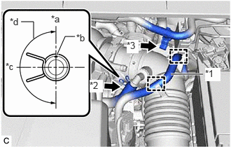
- Connect the No. 2 ventilation hose to the air cleaner hose and slide the clip to secure it.NOTE:
Make sure that the condition of the clip is as shown in the illustration.
*1 No. 1 Fuel Vapor Feed Hose *2 No. 2 Ventilation Hose *3 Vacuum Hose Bracket *a Top *b Paint Mark *c Rear of Vehicle *d 180° (Claw of Clip Location) - Engage the 2 clamps to connect the No. 1 fuel vapor feed hose to the air cleaner hose.
- Install the vacuum hose bracket to the air cleaner hose.
- Install the air cleaner assembly with air cleaner hose to the throttle body with motor assembly.
- INSTALL INLET AIR CLEANER ASSEMBLY
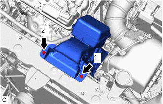
- Install the inlet air cleaner assembly with the 2 bolts in the order shown in the illustration.
Torque: 8.0 N.m (82 kgf/cm, 71 in.lbf)
- Install the inlet air cleaner assembly with the 2 bolts in the order shown in the illustration.
- INSTALL V-BANK COVER SUB-ASSEMBLY
- Engage the 4 clips in the order shown in the illustration to install the V-bank cover sub-assembly.NOTE:
- Securely engage the clips.
- If the clips are forcibly engaged or struck with an object, they may be damaged.
- Engage the 4 clips in the order shown in the illustration to install the V-bank cover sub-assembly.
- INSPECT VACUUM HOSES
- CONNECT CABLE TO NEGATIVE BATTERY TERMINAL NOTE:
When disconnecting the cable, some systems need to be initialized after the cable is reconnected.
Refer to INITIALIZATION [12/2019 - 09/2020]
- ADD ENGINE OIL
Refer to PROCEDURE - Step 5
- ADD ENGINE COOLANT
Refer to PROCEDURE - Step 2
- ADD AUTOMATIC TRANSAXLE FLUID (for 2WD)
Refer to ADJUSTMENT [12/2019 - 10/2022]
- ADD AUTOMATIC TRANSAXLE FLUID (for AWD)
Refer to ADJUSTMENT [12/2019 - 10/2022]
- ADD TRANSFER OIL (for AWD)
Refer to PROCEDURE - Step 2
- CHARGE AIR CONDITIONING SYSTEM WITH REFRIGERANT
Refer to PROCEDURE - Step 2
- WARM UP ENGINE
Refer to PROCEDURE - Step 3
- INSPECT SHIFT LEVER POSITION (for 2WD)
Refer to PROCEDURE - Step 2
- INSPECT SHIFT LEVER POSITION (for AWD)
Refer to PROCEDURE - Step 2
- ADJUST SHIFT LEVER POSITION (for 2WD)
Refer to PROCEDURE - Step 5
- ADJUST SHIFT LEVER POSITION (for AWD)
Refer to PROCEDURE - Step 5
- INSPECT FOR ENGINE OIL LEAK
Refer to PROCEDURE - Step 6
- INSPECT FOR COOLANT LEAK
Refer to PROCEDURE - Step 1
- INSPECT FOR REFRIGERANT LEAK
Refer to PROCEDURE - Step 5
- INSPECT FOR FUEL LEAK
- INSPECT FOR EXHAUST GAS LEAK
Refer to PROCEDURE - Step 6
- CHECK ENGINE OIL LEVEL
Refer to PROCEDURE - Step 1
- INSPECT ENGINE COOLANT LEVEL IN RESERVOIR TANK
Refer to PROCEDURE - Step 2
- INSTALL FRONT BUMPER COVER
Refer to INSTALLATION [12/2019 - 09/2020]
- INSTALL FRONT FENDER APRON SEAL LH
- Install the front fender apron seal LH with the 2 bolts and clip.
Torque: 7.5 N.m (76 kgf/cm, 66 in.lbf)
- Install the front fender apron seal LH with the 2 bolts and clip.
- INSTALL FRONT FENDER APRON SEAL RH
- Install the front fender apron seal RH with the 2 bolts and clip.
Torque: 7.5 N.m (76 kgf/cm, 66 in.lbf)
- Install the front fender apron seal RH with the 2 bolts and clip.
- INSTALL FRONT FLOOR COVER RH
- Install the front floor cover RH with the 5 bolts, 3 screws and 3 clips.
Bolt
Torque: 7.5 N.m (76 kgf/cm, 66 in.lbf)
- Install the front floor cover RH with the 5 bolts, 3 screws and 3 clips.
- INSTALL FRONT FLOOR COVER LH
- Install the front floor cover LH with the 4 bolts, 5 screws and 3 clips.
Bolt
Torque: 7.5 N.m (76 kgf/cm, 66 in.lbf)
- Install the front floor cover LH with the 4 bolts, 5 screws and 3 clips.
- INSTALL REAR ENGINE UNDER COVER RH
- Install the rear engine under cover RH with the bolt, screw and 3 clips.
Bolt
Torque: 7.5 N.m (76 kgf/cm, 66 in.lbf)
- Install the rear engine under cover RH with the bolt, screw and 3 clips.
- INSTALL REAR ENGINE UNDER COVER LH
- Install the rear engine under cover LH with the bolt, screw and 3 clips.
Bolt
Torque: 7.5 N.m (76 kgf/cm, 66 in.lbf)
- Install the rear engine under cover LH with the bolt, screw and 3 clips.
- INSTALL NO. 1 ENGINE UNDER COVER
- Install the No. 1 engine under cover with the 3 bolts, 8 screws and 2 clips.
Bolt
Torque: 7.5 N.m (76 kgf/cm, 66 in.lbf)
- Install the No. 1 engine under cover with the 3 bolts, 8 screws and 2 clips.
- INSTALL FRONT WHEEL OPENING EXTENSION PAD LH
- Install the front wheel opening extension pad LH with the 4 screws.
- INSTALL FRONT WHEEL OPENING EXTENSION PAD RH
- Install the front wheel opening extension pad RH with the 4 screws.
- INSTALL FRONT WHEELS
Refer to PROCEDURE - Step 1
- ALIGN FRONT WHEELS FACING STRAIGHT AHEAD
- INSPECT AND ADJUST FRONT WHEEL ALIGNMENT
Refer to ADJUSTMENT [12/2019 - 09/2020]
- PERFORM INITIALIZATION
Refer to PROCEDURE - Step 6
- INSPECT IGNITION TIMING
See step 9
- INSPECT ENGINE IDLE SPEED
See step 10
- INSPECT CO/HC
See step 12
- CHECK FOR SPEED SENSOR SIGNAL