Adjustment [12/2019 - 10/2022]: Procedure
- REMOVE CONSOLE BOX ASSEMBLY
Refer to REMOVAL [12/2019 - 10/2022]
- REMOVE NO. 1 SWITCH HOLE BASE
Refer to PROCEDURE - Step 20
- REMOVE NO. 1 INSTRUMENT PANEL UNDER COVER SUB-ASSEMBLY
Refer to PROCEDURE - Step 17
- REMOVE FRONT CONSOLE BOX INSERT
Refer to PROCEDURE - Step 42
- ADJUST SHIFT LEVER POSITION NOTE:
Before adjusting the transmission control cable assembly, check that the park/neutral position switch assembly and shift lever are in N.
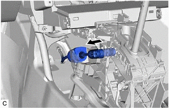
- Disconnect the transmission control cable assembly from the transmission floor shift assembly.
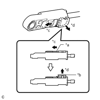
- Slide the slider of the transmission control cable assembly in the direction indicated by the arrow in the illustration and pull the lock piece outward.
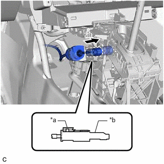
*a Slider *b Lock Piece *c Slide *d Pull - Connect the transmission control cable assembly to the transmission floor shift assembly.NOTE:
- Check that the lock piece is pulled out.
- Push the end of the transmission control cable assembly all the way to the base of the transmission floor shift assembly pin.
- Connect the transmission control cable assembly so that the lock piece faces the driver side.
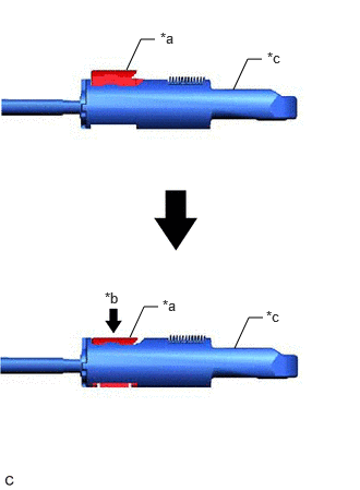
*a Lock Piece *b Adjuster Case - Push the lock piece into the adjuster case.
*a Lock Piece *b Push in *c Adjuster Case NOTE:- Check that the park/neutral position switch assembly and shift lever are in N.
- Securely push in the lock piece until the slider lock is engaged.
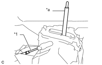
- When pushing in the lock piece of the adjuster case to lock it, remove your hand from the lever shaft.
*1 Transmission Control Cable Assembly *a Lever Shaft - When pushing in the lock piece of the adjuster case to lock it, do not move the lever shaft or transmission control cable assembly forward or backward.
- After adjusting the shift lever position, check the position and operation of the shift lever. If there is a problem, adjust the shift lever position again.
- Disconnect the transmission control cable assembly from the transmission floor shift assembly.
- INSTALL FRONT CONSOLE BOX INSERT
Refer to PROCEDURE - Step 4
- INSTALL NO. 1 INSTRUMENT PANEL UNDER COVER SUB-ASSEMBLY
Refer to PROCEDURE - Step 29
- INSTALL NO. 1 SWITCH HOLE BASE
Refer to PROCEDURE - Step 26
- INSTALL CONSOLE BOX ASSEMBLY
Refer to INSTALLATION [12/2019 - 10/2022]