DSD Information System
Home >> Toyota >> 2021 >> Highlander LE, 4WD >> Repair and Diagnosis >> Body & Frame >> Exterior/Interior Trim >> Interior Body Panels / Trim - Service Information (1 Of 2) >> Instrument Panel Safety Pad >> Removal [12/2019 - 10/2022] >> Procedure

Removal [12/2019 - 10/2022]: Procedure

  1. REMOVE CONSOLE BOX ASSEMBLY 

    Refer to REMOVAL [12/2019 - 10/2022] 

  2. REMOVE FRONT DOOR SCUFF PLATE LH 

    Refer to PROCEDURE - Step 9

  3. REMOVE COWL SIDE TRIM SUB-ASSEMBLY LH 

    Refer to PROCEDURE - Step 10

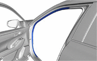
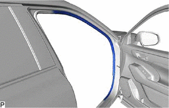
  4. DISCONNECT FRONT DOOR OPENING TRIM WEATHERSTRIP LH 
    1. Disconnect the front door opening trim weatherstrip LH.
      GTY898314Courtesy of © TOYOTA, LICENSE AGREEMENT TMS1002
  5. REMOVE INSTRUMENT PANEL FINISH END PANEL LH 
    1. Using a moulding remover, disengage the 5 clips and 3 guides as shown in the illustration to remove the instrument panel finish end panel LH.
      GTY894976Courtesy of © TOYOTA, LICENSE AGREEMENT TMS1002
      Insert Moulding Remover Here Remove in this Direction
  6. REMOVE NO. 1 INSTRUMENT PANEL REGISTER ASSEMBLY 
    1. Disengage the 4 clips as shown in the illustration to remove the No. 1 instrument panel register assembly.
      GTY908165Courtesy of © TOYOTA, LICENSE AGREEMENT TMS1002
      Remove in this Direction
  7. REMOVE INSTRUMENT PANEL FINISH PANEL SUB-ASSEMBLY 
    1. Disengage the 7 clips and 2 guides as shown in the illustration.
      GTY931012Courtesy of © TOYOTA, LICENSE AGREEMENT TMS1002
      Remove in this Direction
    2. Disconnect each connector to remove the instrument panel finish panel sub-assembly.
  8. REMOVE TRIP SWITCH 

    Refer to PROCEDURE - Step 5

  9. REMOVE INSTRUMENT CLUSTER FINISH PANEL ASSEMBLY 
    1. Disengage the 2 claws and 4 clips to separate the instrument cluster finish panel assembly.
      GTY898264Courtesy of © TOYOTA, LICENSE AGREEMENT TMS1002
    2. Disengage the 9 clips and 2 guides as shown in the illustration to remove the instrument cluster finish panel assembly.
      GTY861379Courtesy of © TOYOTA, LICENSE AGREEMENT TMS1002
      Remove in this Direction
  10. REMOVE COMBINATION METER ASSEMBLY 

    Refer to PROCEDURE - Step 7

  11. REMOVE HORN BUTTON ASSEMBLY 

    Refer to REMOVAL [12/2019 - 10/2022]

  12. REMOVE STEERING WHEEL ASSEMBLY 

    Refer to PROCEDURE - Step 3

  13. REMOVE LOWER STEERING COLUMN COVER 

    Refer to PROCEDURE - Step 5 [12/2019 - 10/2021] , or refer to PROCEDURE - Step 5 [10/2021 - 10/2022]

  14. REMOVE UPPER STEERING COLUMN COVER 

    Refer to PROCEDURE - Step 6 [12/2019 - 10/2021] , or refer to PROCEDURE - Step 6 [10/2021 - 10/2022]

  15. REMOVE TURN SIGNAL SWITCH 

    Refer to PROCEDURE - Step 3

  16. REMOVE WINDSHIELD WIPER SWITCH ASSEMBLY 

    Refer to PROCEDURE - Step 3

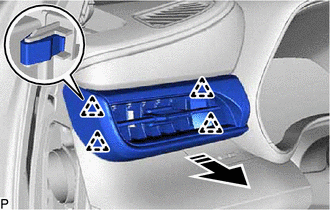
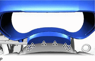
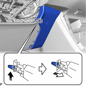
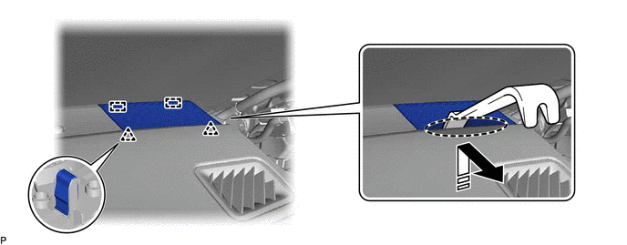
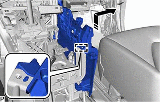
  17. REMOVE NO. 1 INSTRUMENT PANEL UNDER COVER SUB-ASSEMBLY 
    1. Remove the 3 screws <D>.
      GTY898260Courtesy of © TOYOTA, LICENSE AGREEMENT TMS1002
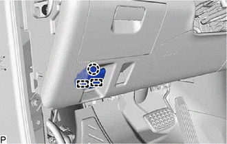
    2. Pull the No. 1 instrument panel under cover sub-assembly in the direction indicated by the arrow (1) shown in the illustration to disengage the 2 claws.
      GTY937321Courtesy of © TOYOTA, LICENSE AGREEMENT TMS1002
      Remove in this Direction (1)
      Remove in this Direction (2)
    3. Pull the No. 1 instrument panel under cover sub-assembly in the direction indicated by the arrow (2) shown in the illustration to disengage the guide.
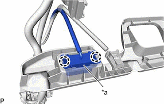
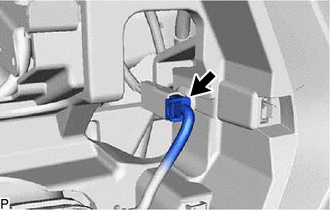
    4. Disengage the 2 claws to disconnect the DLC3.
      GTY883602Courtesy of © TOYOTA, LICENSE AGREEMENT TMS1002
      *a DLC3
    5. Remove the No. 1 instrument panel under cover sub-assembly.
  18. DISCONNECT HOOD LOCK CONTROL LEVER SUB-ASSEMBLY 
    1. Disengage the claw and 2 guides to disconnect the hood lock control lever sub-assembly.
      GTY939420Courtesy of © TOYOTA, LICENSE AGREEMENT TMS1002
  19. REMOVE LOWER INSTRUMENT PANEL FINISH PANEL SUB-ASSEMBLY 
    1. Disengage the 8 clips as shown in the illustration.
      GTY923531Courtesy of © TOYOTA, LICENSE AGREEMENT TMS1002
      Remove in this Direction
    2. Disconnect the connector to remove the lower instrument panel finish panel sub-assembly.
  20. REMOVE NO. 1 SWITCH HOLE BASE 
    1. Disengage the 6 clips as shown in the illustration.
      GTY849572Courtesy of © TOYOTA, LICENSE AGREEMENT TMS1002
      Remove in this Direction
    2. Disengage the hook as shown in the illustration to remove the No. 1 switch hole base.
      GTY855080Courtesy of © TOYOTA, LICENSE AGREEMENT TMS1002
      Remove in this Direction (1)
      Remove in this Direction (2)
  21. REMOVE LOWER NO. 1 INSTRUMENT PANEL AIRBAG ASSEMBLY 

    Refer to PROCEDURE - Step 10

  22. REMOVE CENTER INSTRUMENT CLUSTER FINISH PANEL SUB-ASSEMBLY 
    1. Apply protective tape to the area shown in the illustration.
      GTY865801Courtesy of © TOYOTA, LICENSE AGREEMENT TMS1002
      Protective Tape
    2. Using a moulding remover, disengage the 5 clips and 4 guides as shown in the illustration to remove the center instrument cluster finish panel sub-assembly.
      GTY870377Courtesy of © TOYOTA, LICENSE AGREEMENT TMS1002
      Remove in this Direction
  23. REMOVE RADIO AND DISPLAY ASSEMBLY WITH AIR CONDITIONING CONTROL (for 8 Inch Display) 

    Refer to PROCEDURE - Step 4

  24. REMOVE MULTI-DISPLAY WITH AIR CONDITIONING CONTROL (for 12.3 Inch Display) 

    Refer to PROCEDURE - Step 2

  25. REMOVE CENTER INSTRUMENT CLUSTER FINISH PANEL ASSEMBLY 
    1. Remove the 2 screws <B>.
      GTY898278Courtesy of © TOYOTA, LICENSE AGREEMENT TMS1002
    2. Disconnect the connector.
      GTY898280Courtesy of © TOYOTA, LICENSE AGREEMENT TMS1002
    3. Disengage the 2 claws and 16 clips as shown in the illustration.
      GTY900966Courtesy of © TOYOTA, LICENSE AGREEMENT TMS1002
      Remove in this Direction
    4. Disengage the clamp to remove the center instrument cluster finish panel assembly.
      GTY898277Courtesy of © TOYOTA, LICENSE AGREEMENT TMS1002
    5. w/ Interior Illumination:
      1. Disconnect the 2 connectors.
      2. Disengage the clamp.
        GTY924157Courtesy of © TOYOTA, LICENSE AGREEMENT TMS1002
  26. REMOVE RADIO RECEIVER ASSEMBLY WITH BRACKET (for 12.3 Inch Display) 

    Refer to PROCEDURE - Step 12

  27. REMOVE FRONT DOOR SCUFF PLATE RH 

    HINT: 

    Use the same procedure as for the LH side.

  28. REMOVE COWL SIDE TRIM SUB-ASSEMBLY RH 

    HINT: 

    Use the same procedure as for the LH side.

  29. DISCONNECT FRONT DOOR OPENING TRIM WEATHERSTRIP RH 
    1. Disconnect the front door opening trim weatherstrip RH.
      GTY939427Courtesy of © TOYOTA, LICENSE AGREEMENT TMS1002
  30. REMOVE INSTRUMENT PANEL FINISH END PANEL RH 
    1. Using a moulding remover, disengage the 5 clips and 3 guides as shown in the illustration to remove the instrument panel finish end panel RH.
      GTY887209Courtesy of © TOYOTA, LICENSE AGREEMENT TMS1002
      Insert Moulding Remover Here Remove in this Direction
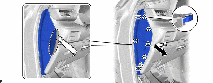
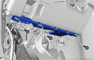
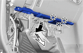
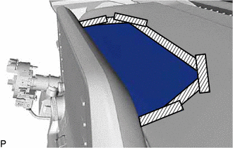
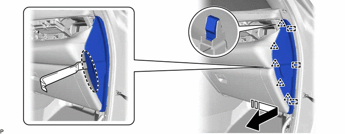
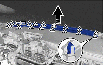
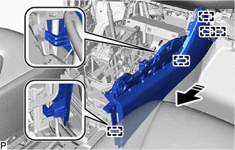
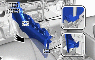
  31. REMOVE NO. 2 INSTRUMENT PANEL UNDER COVER SUB-ASSEMBLY 
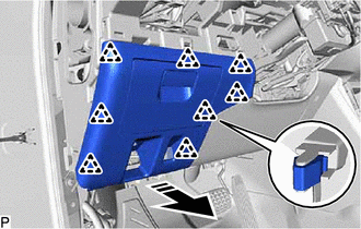
    1. Pull the No. 2 instrument panel under cover sub-assembly in the direction indicated by the arrow (1) shown in the illustration to disengage the 4 claws.
      GTY912441Courtesy of © TOYOTA, LICENSE AGREEMENT TMS1002
      Remove in this Direction (1)
      Remove in this Direction (2)
    2. Pull the No. 2 instrument panel under cover sub-assembly in the direction indicated by the arrow (2) shown in the illustration to disengage the 2 guides to remove it.
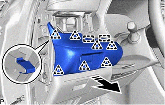
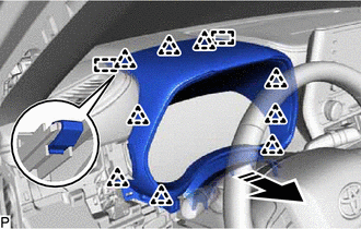
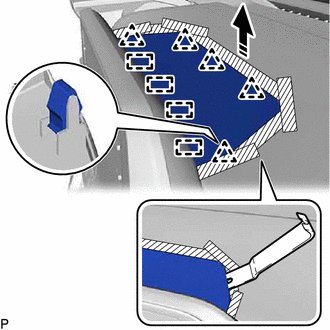
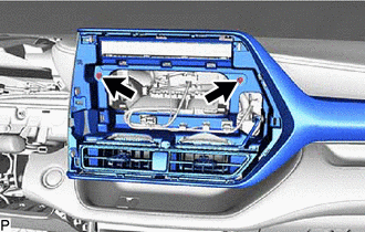
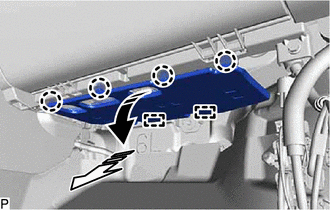
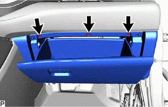
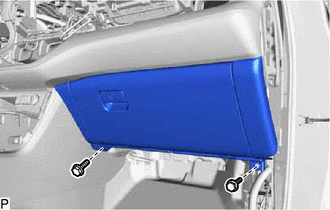
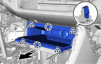
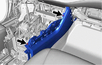
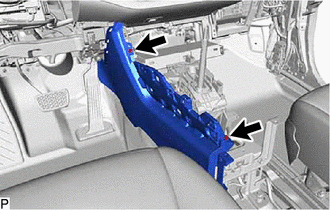
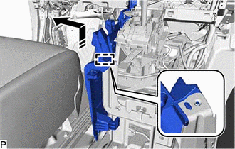
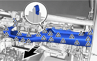
  32. REMOVE LOWER INSTRUMENT PANEL SUB-ASSEMBLY 
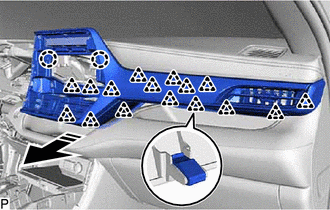
    1. Open the glove compartment door sub-assembly.
    2. Remove the 3 screws <D>.
      GTY898231Courtesy of © TOYOTA, LICENSE AGREEMENT TMS1002
    3. Close the glove compartment door sub-assembly.
    4. Remove the 2 bolts <A>.
      GTY939408Courtesy of © TOYOTA, LICENSE AGREEMENT TMS1002
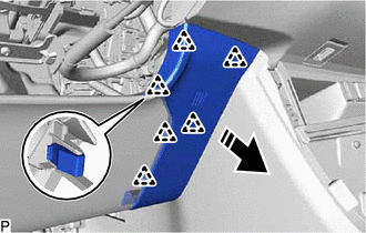
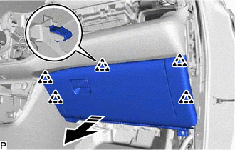
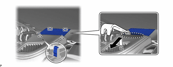
    5. Disengage the 5 clips as shown in the illustration.
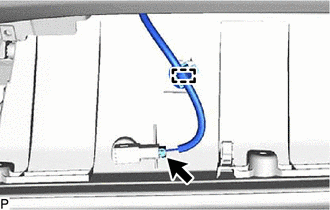
      GTY927555Courtesy of © TOYOTA, LICENSE AGREEMENT TMS1002
      Remove in this Direction
    6. Disconnect the connector.
      GTY898228Courtesy of © TOYOTA, LICENSE AGREEMENT TMS1002
    7. Disengage the clamp to remove the lower instrument panel sub-assembly.
  33. REMOVE FRONT PILLAR GARNISH ASSEMBLY LH 

    Refer to PROCEDURE - Step 12

  34. REMOVE NO. 1 INSTRUMENT PANEL SPEAKER PANEL 
    1. Using a moulding remover, disengage the 2 clips and 2 guides as shown in the illustration to remove the No. 1 instrument panel speaker panel.
      GTY883654Courtesy of © TOYOTA, LICENSE AGREEMENT TMS1002
      Insert Moulding Remover Here Remove in this Direction
  35. REMOVE FRONT NO. 2 SPEAKER ASSEMBLY (for LH Side) 

    Refer to PROCEDURE - Step 2

  36. REMOVE FRONT PILLAR GARNISH ASSEMBLY RH 

    HINT: 

    Use the same procedure as for the LH side.

  37. REMOVE NO. 2 INSTRUMENT PANEL SPEAKER PANEL 
    1. Using a moulding remover, disengage the 2 clips and 2 guides as shown in the illustration to remove the No. 2 instrument panel speaker panel.
      GTY937388Courtesy of © TOYOTA, LICENSE AGREEMENT TMS1002
      Insert Moulding Remover Here Remove in this Direction
  38. REMOVE FRONT NO. 2 SPEAKER ASSEMBLY (for RH Side) 

    HINT: 

    Use the same procedure as for the LH side.

  39. REMOVE NO. 1 DEFROSTER NOZZLE GARNISH 
    1. Disengage the 17 clips and 2 guides as shown in the illustration.
      GTY856361Courtesy of © TOYOTA, LICENSE AGREEMENT TMS1002
      Remove in this Direction
    2. Disconnect the connector to remove the No. 1 defroster nozzle garnish.
  40. REMOVE LOWER CENTER INSTRUMENT PANEL FINISH PANEL 
    1. Disengage the 2 claws and 4 clips as shown in the illustration.
      GTY876852Courtesy of © TOYOTA, LICENSE AGREEMENT TMS1002
      Remove in this Direction
    2. Disconnect each connector to remove the lower center instrument panel finish panel.
  41. REMOVE FRONT NO. 2 CONSOLE BOX INSERT 
    1. Remove the 2 screws <D>.
      GTY941489Courtesy of © TOYOTA, LICENSE AGREEMENT TMS1002
    2. Disengage the guide as shown in the illustration.
      GTY880273Courtesy of © TOYOTA, LICENSE AGREEMENT TMS1002
      Remove in this Direction
    3. Disengage the 5 guides as shown in the illustration to remove the front No. 2 console box insert.
      GTY890707Courtesy of © TOYOTA, LICENSE AGREEMENT TMS1002
      Remove in this Direction
  42. REMOVE FRONT CONSOLE BOX INSERT 
    1. Remove the 2 screws <D>.
      GTY907605Courtesy of © TOYOTA, LICENSE AGREEMENT TMS1002
    2. Disengage the guide as shown in the illustration.
      GTY945438Courtesy of © TOYOTA, LICENSE AGREEMENT TMS1002
      Remove in this Direction
    3. Disengage the 5 guides as shown in the illustration to remove the front console box insert.
      GTY928407Courtesy of © TOYOTA, LICENSE AGREEMENT TMS1002
      Remove in this Direction
  43. REMOVE INSTRUMENT CLUSTER FINISH PANEL ORNAMENT 
    1. Disengage the 22 clips as shown in the illustration.
      GTY896501Courtesy of © TOYOTA, LICENSE AGREEMENT TMS1002
      Remove in this Direction
    2. Disconnect the connector to remove the instrument cluster finish panel ornament.
  44. REMOVE DCM (TELEMATICS TRANSCEIVER) WITH BRACKET (w/ Manual (SOS) Switch) 

    Refer to PROCEDURE - Step 15

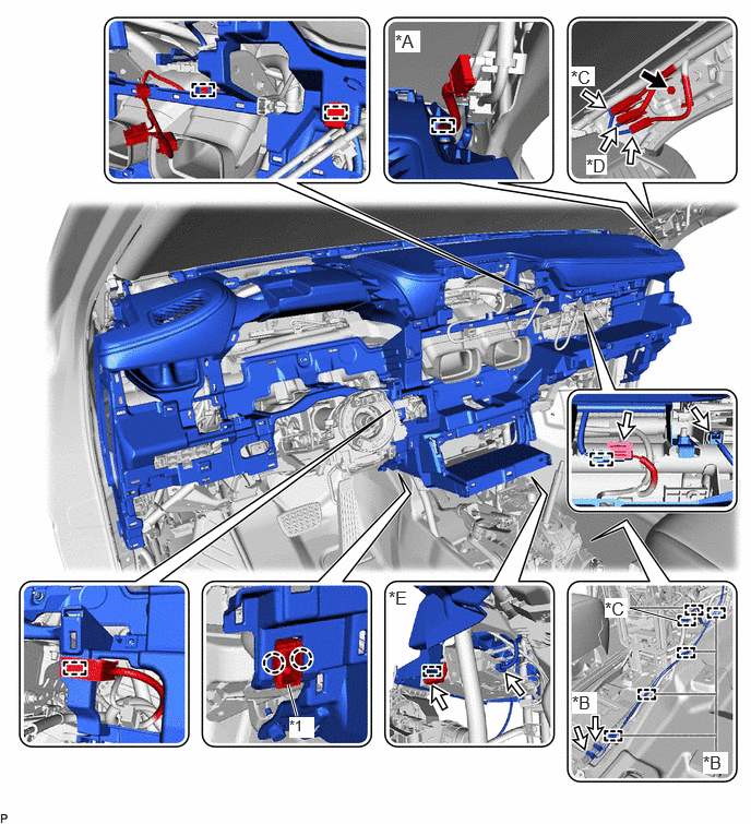
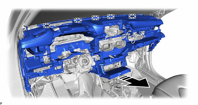
  45. REMOVE INSTRUMENT PANEL SAFETY PAD SUB-ASSEMBLY 
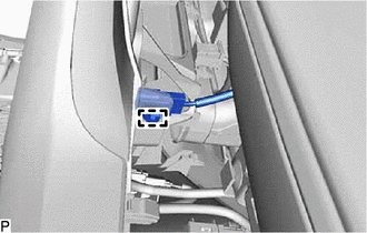
    1. Disengage the 2 claws to disconnect the cooler (room temp. sensor) thermistor.
      GTY1015491Courtesy of © TOYOTA, LICENSE AGREEMENT TMS1002
      *A for 11 Speakers *B for 12.3 Inch Display
      *C w/ Rear Seat Entertainment System *D w/ Manual (SOS) Switch
      *E w/ Navigation System - -
      *1 Cooler (Room Temp. Sensor) Thermistor - -
    2. Remove the bolt <F>.
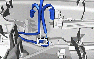
    3. Disconnect each connector.
    4. Disconnect the airbag connector.

      HINT: 

      Refer to How to Connect or Disconnect Airbag Connector.

      Refer to HOW TO CONNECT OR DISCONNECT AIRBAG CONNECTOR [12/2019 - 11/2023]

    5. Disengage each clamp.
    6. Remove the 2 clips.
      GTY940333Courtesy of © TOYOTA, LICENSE AGREEMENT TMS1002
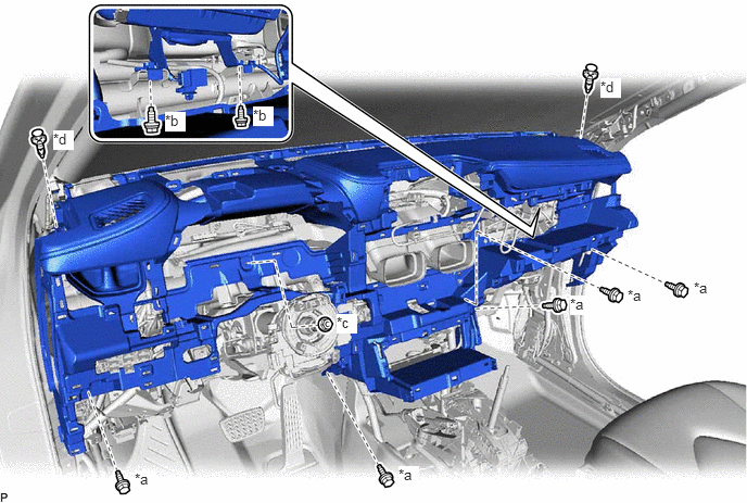
      *a Bolt <A> *b Bolt <E>
      *c Nut <C> *d Clip
    7. Remove the 5 bolts <A>, 2 bolts <E> and nut <C>.
    8. Disengage the 5 guides as shown in the illustration to remove the instrument panel safety pad sub-assembly.
      GTY907807Courtesy of © TOYOTA, LICENSE AGREEMENT TMS1002
      Remove in this Direction - -
      NOTE:
      • Do not damage the instrument panel safety pad sub-assembly.
      • Do not allow the wire harnesses to interfere with the surrounding parts.