On-Vehicle Inspection [12/2019 - ]: Procedure
- INSPECT ENGINE COOLANT (for Engine)
Refer to ON-VEHICLE INSPECTION [12/2019 - ]
- INSPECT ENGINE OIL
Refer to ON-VEHICLE INSPECTION [12/2019 - 11/2023] , or refer to ON-VEHICLE INSPECTION [11/2023 - ]
- INSPECT AUXILIARY BATTERY
Refer to ON-VEHICLE INSPECTION [12/2019 - 11/2023] , or refer to ON-VEHICLE INSPECTION [11/2023 - ]
- INSPECT SPARK PLUG
Refer to ON-VEHICLE INSPECTION [12/2019 - ]
- INSPECT AIR CLEANER FILTER ELEMENT SUB-ASSEMBLY
- Remove the air cleaner filter element sub-assembly.
- Visually check that the air cleaner filter element sub-assembly is not damaged or excessively oily.
HINT:
- If there is any dirt or clogs in the air cleaner filter element sub-assembly, clean it with compressed air.
- If any dirt or clogs remain even after cleaning the air cleaner filter element sub-assembly with compressed air, replace it.
- Install the air cleaner filter element sub-assembly.
- INSPECT VALVE LASH ADJUSTER ASSEMBLY NOISE
- Put the engine in inspection mode.
- Rev up the engine several times. Check that the engine does not emit unusual noises.
- If unusual noises occur, warm up the engine and idle it for 30 minutes or more, then perform the inspection.
HINT:
If any defects or problems are found during the inspection, perform valve lash adjuster assembly inspection.
Refer to PROCEDURE - Step 2
- INSPECT IGNITION TIMING NOTE:
- Check the ignition timing with the cooling fan off.
- Turn off all electrical systems and the A/C.
- When checking the ignition timing, the transaxle should be in park.
- Put the engine in inspection mode.
- Warm up and stop the engine.
- Put the engine in inspection mode.
- Monitor Ignition Timing Cylinder #1 of the Data List.
Powertrain > Engine > Data List
Tester Display Ignition Timing Cylinder #1 Standard Ignition Timing
-2 to 14° BTDC at idle
- Check that the ignition timing advances immediately when the engine speed is increased.
- Monitor Ignition Timing Cylinder #1 of the Data List.
Powertrain > Engine > Active Test
Active Test Display Activate the TC Terminal Data List Display Ignition Timing Cylinder #1 Standard Ignition Timing
8 to 12° BTDC at idle
- INSPECT ENGINE IDLE SPEED NOTE:
- Check the engine idle speed with the cooling fan off.
- Turn off all electrical systems and the A/C.
- When checking the engine idle speed, the transaxle should be in park.
- INSPECT COMPRESSION NOTE:
Keep the spark plug holes free of foreign matter when measuring the compression pressure.
- Put the engine in inspection mode.
- Warm up and stop the engine.
- Check for DTCs.
Refer to DTC CHECK / CLEAR [12/2019 - 10/2022] , or refer to DTC CHECK / CLEAR [10/2022 - 11/2023] , or refer to DTC CHECK / CLEAR [11/2023 - ]
- Remove the front wheel opening extension pad LH.
See step 7[12/2019 - 10/2022], or refer to PROCEDURE - Step 7 [10/2022 - 11/2023] , or refer to PROCEDURE - Step 7 [11/2023 - ]
- Remove the front wheel opening extension pad RH.
See step 8[12/2019 - 10/2022], or refer to PROCEDURE - Step 8 [10/2022 - 11/2023] , or refer to PROCEDURE - Step 8 [11/2023 - ]
- Remove the No. 1 engine under cover.
See step 9[12/2019 - 10/2022], or refer to PROCEDURE - Step 9 [10/2022 - 11/2023] , or refer to PROCEDURE - Step 9 [11/2023 - ]
- Remove the cool air intake dust seal.
Refer to PROCEDURE - Step 1 [12/2019 - 09/2020] , or refer to PROCEDURE - Step 1 [09/2020 - 11/2023] , or refer to PROCEDURE - Step 1 [11/2023 - ]
- Remove the intake air cleaner assembly.
Refer to PROCEDURE - Step 6 [12/2019 - 10/2022] , or refer to PROCEDURE - Step 6 [10/2022 - 11/2023] , or refer to PROCEDURE - Step 6 [11/2023 - ]
- Remove the air cleaner cap with air cleaner hose.
Refer to PROCEDURE - Step 5 [12/2019 - 09/2020] , or refer to PROCEDURE - Step 5 [09/2020 - ]
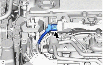
- Disconnect the fuel injector connector (for Port Injection).
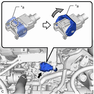
- Disengage the claw and raise the lock lever to disconnect the No. 6 engine wire connector as shown in the illustration.
*a Lock Lever NOTE:Perform this step in order to stop fuel injection and prevent damage to the catalyst due to unburned fuel.
- Remove the 4 spark plugs.
Refer to REMOVAL [12/2019 - ]
NOTE:DTCs will be stored if the inspection is performed with the ignition coil assembly connectors disconnected. Make sure that the ignition coil assembly connectors are connected during the inspection.
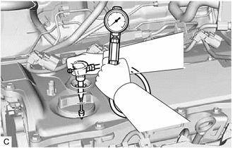
- Check the cylinder compression pressure.
- Insert a compression gauge into the spark plug hole.
- Depress and hold the brake pedal, and turn the ignition switch to ON (READY). Then check the compression pressure.
Powertrain > Hybrid Control > Active Test
Tester Display Compression Test Standard Compression Pressure
870 kPa (8.9 kgf/cm 2 , 126 psi)
Minimum Compression Pressure
700 kPa (7.1 kgf/cm 2 , 102 psi)
Pressure Difference between Each Cylinder
200 kPa (2.0 kgf/cm 2 , 29 psi) or less
NOTE:- Check the HV battery voltage in the Data List to ensure that the auxiliary battery is fully charged.
- Noise may be emitted from the hybrid vehicle transaxle assembly. However, this is not a malfunction.
- Inspect all cylinders in the same way.
- Measure the compression pressure as quickly as possible.
- If the cylinder compression pressure is low, pour a small amount of engine oil into the cylinder through the spark plug hole and inspect it again.
HINT:
- If adding oil increases the compression pressure, the piston rings and/or cylinder bore may be worn or damaged.
- If the compression pressure stays low, a valve may be stuck or seated improperly, or there may be leaks in the cylinder head gasket.
- Insert a compression gauge into the spark plug hole.
- Install the 4 spark plugs.
Refer to INSTALLATION [12/2019 - ]
- Install the air cleaner cap with air cleaner hose.
Refer to PROCEDURE - Step 3 [12/2019 - 09/2020] , or refer to PROCEDURE - Step 3 [09/2020 - ]
- Install the inlet air cleaner assembly.
Refer to PROCEDURE - Step 20 [12/2019 - 11/2023] , or refer to PROCEDURE - Step 20 [11/2023 - ]
- Install the cool air intake dust seal.
Refer to PROCEDURE - Step 4 [12/2019 - 09/2020] , or refer to PROCEDURE - Step 4 [09/2020 - ]
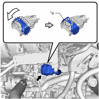
- Connect the No. 6 engine wire connector and push down the lock lever to engage the claw as shown in the illustration.
*a Lock Lever - Connect the fuel injector connector (for Port Injection).
- Install the No. 1 engine under cover.
Refer to PROCEDURE - Step 63 [12/2019 - 10/2022] , or refer to PROCEDURE - Step 63 [10/2022 - 11/2023] , or refer to PROCEDURE - Step 61 [11/2023 - ]
- Install the front wheel opening extension pad LH.
Refer to PROCEDURE - Step 64 [12/2019 - 10/2022] , or refer to PROCEDURE - Step 64 [10/2022 - 11/2023] , or refer to PROCEDURE - Step 62 [11/2023 - ]
- Install the front wheel opening extension pad RH.
Refer to PROCEDURE - Step 65 [12/2019 - 10/2022] , or refer to PROCEDURE - Step 65 [10/2022 - 11/2023] , or refer to PROCEDURE - Step 63 [11/2023 - ]
- Clear the DTCs.
Refer to DTC CHECK / CLEAR [12/2019 - 10/2022] , or refer to DTC CHECK / CLEAR [10/2022 - 11/2023] , or refer to DTC CHECK / CLEAR [11/2023 - ]
NOTE:After performing the inspection, clear the DTCs and confirm that DTCs are not stored again or that the normal system code is output if using a check wire.
- INSPECT CO/HC
HINT:
This check determines whether or not the idle CO/HC complies with regulations.
- Put the engine in inspection mode.
- Run the engine speed at 2500 rpm for approximately 180 seconds.
- Insert a CO/HC meter testing probe at least 40 cm (1.31 ft.) into the tailpipe during idle.
- Immediately check the CO/HC concentration at idle and then at an engine speed of 2500 rpm.
HINT:
When performing a 2 mode test (with the engine idling/running at 2500 rpm), the measurement procedures are determined by applicable local regulations.
If the CO/HC concentration does not comply with the regulations, perform troubleshooting in the order given below.
- Check for DTCs.
Refer to DTC CHECK / CLEAR [12/2019 - 10/2022] , or refer to DTC CHECK / CLEAR [10/2022 - 11/2023] , or refer to DTC CHECK / CLEAR [11/2023 - ]
- See the following table for possible causes, then inspect the applicable parts and repair them if necessary.
CO HC Problem Cause Normal High Rough idle - Faulty ignition:
- Incorrect valve timing
- Fouled, shorted or improperly gapped spark plugs
- Incorrect valve clearance (valve lash adjuster assembly)
- Leaks in intake or exhaust valves
- Leaks in cylinders
- Faulty EGR
Low High Rough idle (Fluctuating HC reading) - Vacuum leaks:
- PCV hoses
- Intake manifold
- Throttle body with motor assembly
- Lean mixture causing misfire
- Faulty EGR
High High Rough idle (Black smoke from exhaust) - Restricted air cleaner filter element sub-assembly
- Plugged PCV valve
- Faulty SFI systems:
- Fuel pressure regulator assembly
- Engine coolant temperature sensor
- Mass air flow meter sub-assembly
- ECM
- Fuel injector assemblies
- Throttle position sensor (built into throttle body with motor assembly)
- Faulty EGR
- Faulty ignition:
- Check for DTCs.