Installation [12/2019 - 11/2023]: Procedure
- INSTALL HYBRID INVERTER PROTECTOR ASSEMBLY
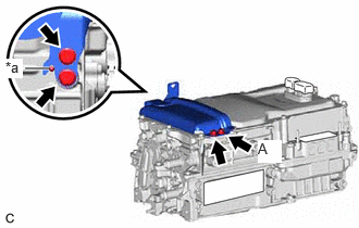
- Temporarily install the hybrid inverter protector assembly to the inverter with converter assembly with the 4 bolts.NOTE:
Make sure to align the guide of the hybrid inverter protector assembly with the pin.
*a Pin - Fully tighten the bolt (A).
Torque: 8.0 N.m (82 kgf/cm, 71 in.lbf)
- Fully tighten the 3 bolts to install the hybrid inverter protector assembly to the inverter with converter assembly.
Torque: 8.0 N.m (82 kgf/cm, 71 in.lbf)
- Temporarily install the hybrid inverter protector assembly to the inverter with converter assembly with the 4 bolts.
- INSTALL WIRE HARNESS CLAMP BRACKET
- Install the wire harness clamp bracket to the inverter with converter assembly with the 2 bolts.
Torque: 8.0 N.m (82 kgf/cm, 71 in.lbf)
- Install the wire harness clamp bracket to the inverter with converter assembly with the 2 bolts.
Torque: 10 N.m (102 kgf/cm, 7 ft.lbf)
- Install the wire harness clamp bracket to the inverter with converter assembly with the bolt.
Torque: 10 N.m (102 kgf/cm, 7 ft.lbf)
- Install the wire harness clamp bracket to the inverter with converter assembly with the 2 bolts.
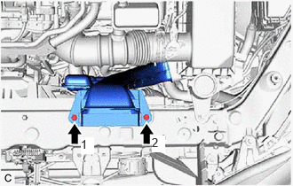
- INSTALL NO. 2 INVERTER BRACKET NOTE:
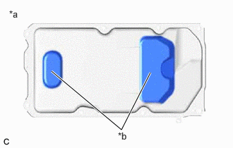
Make sure to support the inverter with converter assembly at the positions shown in the illustration, otherwise it may be damaged.
*a Bottom of Inverter with Converter Assembly *b Support - Set the inverter with converter assembly on wooden blocks.
 Courtesy of © TOYOTA, LICENSE AGREEMENT TMS1002
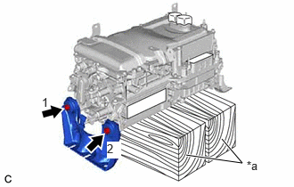
*a Wooden Block - Temporarily install the No. 2 inverter bracket to the inverter with converter assembly with the 2 bolts.
- Fully tighten the 2 bolts in the order shown in the illustration.
Torque: 15 N.m (153 kgf/cm, 11 ft.lbf)
- Set the inverter with converter assembly on wooden blocks.
- INSTALL NO. 1 INVERTER BRACKET
- INSTALL INVERTER WITH CONVERTER ASSEMBLY WARNING:
Be sure to wear insulated gloves.
- Temporarily install the inverter with converter assembly with the 5 bolts and 2 nuts.NOTE:
- When installing the inverter with converter assembly, be careful not to damage the parts around it.
- To prevent damage, do not hold the inverter with converter assembly by the connectors, brackets or cooling pipes.
- To prevent damage due to static electricity, do not touch the terminals of the disconnected connectors.
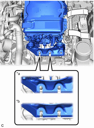
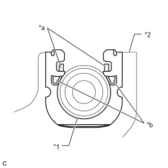
- Make sure that the inverter with converter assembly is positioned so that the stud bolts are in contact with the base of the U-shaped portions of the No. 1 inverter bracket.
*a Correct *b Incorrect
HINT:
If the bolts and nuts are not tightened appropriately, the inverter with converter assembly may make an abnormal noise.
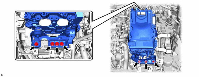
- Fully tighten the bolt (A).
Torque: 55 N.m (561 kgf/cm, 41 ft.lbf)
- Fully tighten the 3 bolts (B).
Torque: 55 N.m (561 kgf/cm, 41 ft.lbf)
- Fully tighten the bolt (C).
Torque: 55 N.m (561 kgf/cm, 41 ft.lbf)
- Fully tighten the 2 nuts (D).
Torque: 55 N.m (561 kgf/cm, 41 ft.lbf)
- Temporarily install the inverter with converter assembly with the 5 bolts and 2 nuts.
- INSTALL WIRE HARNESS CLAMP BRACKET
- Install the wire harness clamp bracket to the inverter with converter assembly with the 2 bolts.
Torque: 8.0 N.m (82 kgf/cm, 71 in.lbf)
- Install the wire harness clamp bracket to the inverter with converter assembly with the 2 bolts.
- CONNECT MOTOR CABLE WARNING:
Be sure to wear insulated gloves.
NOTE:Do not allow any foreign matter or water to enter the inverter with converter assembly.
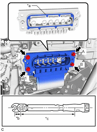
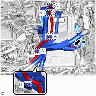
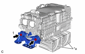
- Temporarily connect the motor cable to the inverter with converter assembly with the 4 bolts.NOTE:
- Do not touch the waterproof seal or terminals of the connector.
- Do not damage the terminals, connector housing or inverter with converter assembly during disconnection.
- Fully tighten the bolt (A).
*a Waterproof Seal *b 10 mm Union Nut Wrench Fulcrum Length *c Torque Wrench Fulcrum Length Torque: 8.0 N.m (82 kgf/cm, 71 in.lbf)
- Fully tighten the 2 bolts in the order shown in the illustration.
Torque: 8.0 N.m (82 kgf/cm, 71 in.lbf)
- Using a 10 mm union nut wrench, fully tighten the bolt (B) to connect the motor cable to the inverter with converter assembly.
Specified tightening torque
Torque: 8.0 N.m (82 kgf/cm, 71 in.lbf)
HINT:
- Calculate the torque wrench reading when changing the fulcrum length of the torque wrench.
- When using a 10 mm union nut wrench (fulcrum length of 22 mm (0.866 in.)) + torque wrench (fulcrum length of 162 mm (6.38 in.)):
7.0 N.m (71 kgf/cm, 62 in.lbf)
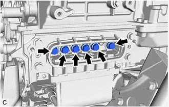
- Temporarily install the 6 bolts.NOTE:
- To prevent the threads from being damaged, temporarily tighten the 6 bolts by hand.
- Do not damage the terminals, connector housing or inverter with converter assembly during disconnection.
- Do not touch the waterproof seal or terminals of the connector.
- Using an insulated tool, fully tighten the 6 bolts.
Torque: 8.0 N.m (82 kgf/cm, 71 in.lbf)
NOTE:- Do not touch the waterproof seal or terminals of the connector.
- Do not damage the terminals, connector housing or inverter with converter assembly during disconnection.
- Be sure to use a torque wrench to tighten the bolts.
- Temporarily connect the motor cable to the inverter with converter assembly with the 4 bolts.
- INSTALL INVERTER COVER WARNING:
Be sure to wear insulated gloves.
- Install the inverter cover to the inverter with converter assembly with the 2 bolts.
Torque: 8.0 N.m (82 kgf/cm, 71 in.lbf)
NOTE:- Visually confirm that the inverter cover waterproof seal is securely installed before installing the inverter cover.
- Do not touch the waterproof seal of the inverter cover.
- Make sure that the interlock is fully engaged.
- Do not damage the terminals, interlock connector or inverter with converter assembly during installation.
- Do not allow any foreign matter or water to enter the inverter with converter assembly.
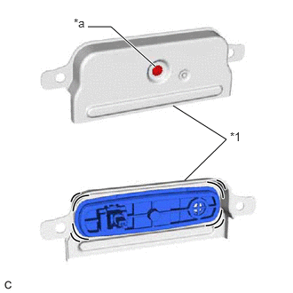
- Do not remove or excessively tighten the screw of the inverter cover.
*1 Inverter Cover *a Screw - Although the inverter cover may feel loose, this is not due to a malfunction.
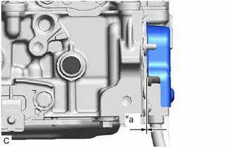
- Push in the inverter cover until it contacts the inverter with converter assembly.
*a No Gap
- Install the inverter cover to the inverter with converter assembly with the 2 bolts.
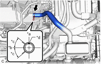
- CONNECT NO. 4 INVERTER COOLING HOSE
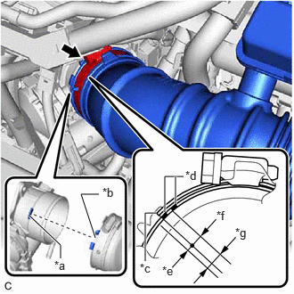
- Connect the No. 4 inverter cooling hose to the inverter with converter assembly and slide the clip to secure it.NOTE:
- To prevent foreign matter from entering the inverter with converter assembly and inverter cooling system, do not remove the pieces of cloth from the pipe and disconnected hose until installation.
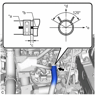
- Make sure to align the alignment mark of the hose with the rib of the inverter with converter assembly.
*a Alignment Mark *b Rib *c 2 to 7 mm (0.0787 to 0.276 in.) *d Up *e LH Side HINT:
Make sure that the clip is positioned as shown in the illustration.
- Connect the No. 4 inverter cooling hose to the inverter with converter assembly and slide the clip to secure it.
- CONNECT NO. 1 INVERTER COOLING HOSE
- Connect the No. 1 inverter cooling hose to the inverter with converter assembly and slide the clip to secure it.NOTE:
- To prevent foreign matter from entering the inverter with converter assembly and inverter cooling system, do not remove the pieces of cloth from the pipe and disconnected hose until installation.
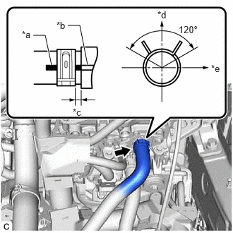
- Make sure to align the alignment mark of the hose with the rib of the inverter with converter assembly.
HINT:
Make sure that the clip is positioned as shown in the illustration.
*a Alignment Mark *b Rib *c 2 to 7 mm (0.0787 to 0.276 in.) *d Up *e LH Side
- Connect the No. 1 inverter cooling hose to the inverter with converter assembly and slide the clip to secure it.
- CONNECT TRANSMISSION CONTROL CABLE ASSEMBLY
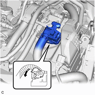
- Connect the transmission control cable assembly to the inverter with converter assembly with the 2 bolts.
Torque: 12 N.m (122 kgf/cm, 9 ft.lbf)
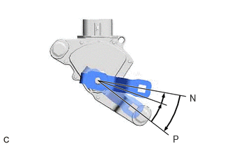
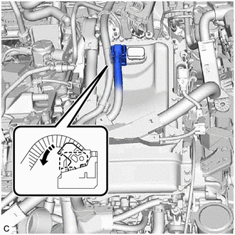
- Turn the control shaft lever clockwise until it stops, then turn it counterclockwise 2 notches.
- Engage the 2 claws to install a new clip to the transmission control cable assembly.
- Using a screwdriver, engage the 4 claws and connect the transmission control cable assembly to the No. 1 transmission control cable bracket.
*1 Transmission Control Cable Assembly *2 No. 1 Transmission Control Cable Bracket *a Claw (A) *b Claw (B) NOTE:- Make sure that the claws (A) of the clip are securely engaged in the grooves of the bracket.
- Make sure that the transmission control cable assembly is securely installed inside of the claws (B) of the clip.
- Connect the transmission control cable assembly to the control shaft lever with the nut.
Torque: 12 N.m (122 kgf/cm, 9 ft.lbf)
- Connect the transmission control cable assembly to the inverter with converter assembly with the 2 bolts.
- CONNECT ENGINE WIRE WARNING:
Be sure to wear insulated gloves.
NOTE:Do not allow any foreign matter or water to enter the inverter with converter assembly.
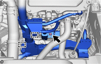
- Engage the 2 clamps to connect the engine wire to the inverter with converter assembly.
- Temporarily install the nut.NOTE:
To prevent the threads from being damaged, temporarily tighten the nut by hand.
- Fully tighten the nut.
Torque: 10 N.m (102 kgf/cm, 7 ft.lbf)
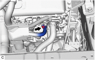
- Engage the 2 claws to close the engine wire terminal cover.
- Connect the engine wire to the inverter with converter assembly with the bolt.
Torque: 10 N.m (102 kgf/cm, 7 ft.lbf)
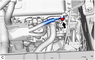
- Connect the engine wire to the inverter with converter assembly with the bolt.
Torque: 10 N.m (102 kgf/cm, 7 ft.lbf)
- Engage the 2 clamps.
- Engage the clamp.
- Confirm that no foreign matter or water has entered the connector of the generator temperature sensor, resolver (transmission fluid temperature sensor) and shift lever position sensor and connect the 3 connectors.
- Engage the 2 clamps (B).
- Connect the engine wire to the inverter with converter assembly with the bolt.
Torque: 10 N.m (102 kgf/cm, 7 ft.lbf)
- Engage the 3 clamps (A) to connect the No. 1 fuel vapor feed hose.
- Connect the inverter with converter assembly connector and move the lock lever to lock them.NOTE:
- Do not touch the waterproof seal or terminals of the connector.
- To prevent damage due to static electricity, do not touch the terminals of the disconnected connector.
- Do not damage the terminals, connector housing or inverter with converter assembly when connecting the connector.
- Engage the 2 clamps to connect the engine wire to the inverter with converter assembly.
- INSTALL WIRE HARNESS CLAMP BRACKET
- Install the wire harness clamp bracket to the inverter with converter assembly with the nut.
Torque: 10 N.m (102 kgf/cm, 7 ft.lbf)
- Install the wire harness clamp bracket to the inverter with converter assembly with the nut.
- CONNECT HV AIR CONDITIONING WIRE WARNING:
Be sure to wear insulated gloves.
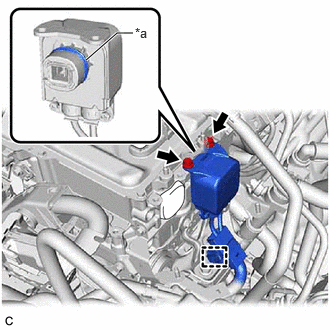
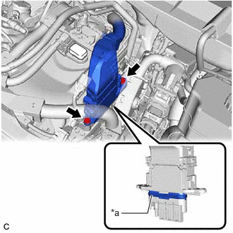
- Engage the clamp to connect the HV air conditioning wire to the inverter with converter assembly.NOTE:
- Do not allow any foreign matter or water to enter the inverter with converter assembly.
- Do not touch the waterproof seal or terminals of the connector.
- Do not damage the terminals, connector housing or inverter with converter assembly when connecting the connector.
*a Waterproof Seal - Install the 2 bolts.
Torque: 8.0 N.m (82 kgf/cm, 71 in.lbf)
- Engage the clamp to connect the HV air conditioning wire to the inverter with converter assembly.
- CONNECT FLOOR UNDER WIRE WARNING:
Be sure to wear insulated gloves.
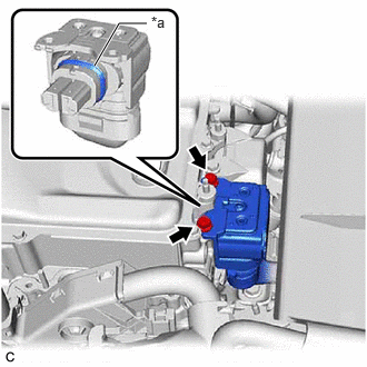
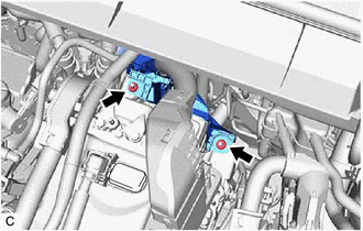
- Install the 2 bolts to connect the HV floor under wire to the inverter with converter assembly.
Torque: 8.0 N.m (82 kgf/cm, 71 in.lbf)
NOTE:- Do not allow any foreign matter or water to enter the inverter with converter assembly.
- Do not touch the waterproof seal or terminals of the connector.
- Do not damage the terminals, connector housing or inverter with converter assembly when connecting the connector.
*a Waterproof Seal - Connect the HV floor under wire to the inverter with converter assembly with the 2 nuts.
Torque: 8.0 N.m (82 kgf/cm, 71 in.lbf)
- for AWD:
- Connect the HV floor under wire to the inverter with converter assembly with the 2 bolts.
Torque: 8.0 N.m (82 kgf/cm, 71 in.lbf)
NOTE:- Make sure that the connector is fully engaged.
- Do not damage the terminals, interlock connector or inverter with converter assembly during installation.
- Do not touch the waterproof seal or terminals of the connector.
- Do not allow any foreign matter or water to enter the inverter with converter assembly.
- Although the connector may feel loose, this is not due to a malfunction.
*a Waterproof Seal
- Connect the HV floor under wire to the inverter with converter assembly with the 2 bolts.
- Install the 2 bolts to connect the HV floor under wire to the inverter with converter assembly.
- CONNECT ENGINE ROOM MAIN WIRE WARNING:
Be sure to wear insulated gloves.
- Engage the clamp to connect the engine room main wire to the inverter with converter assembly.
- Install the bolt.
Torque: 8.0 N.m (82 kgf/cm, 71 in.lbf)
- Connect the inverter with converter assembly connector and move the lock lever to lock them.NOTE:
- Do not touch the waterproof seal or terminals of the connector.
- To prevent damage due to static electricity, do not touch the terminals of the disconnected connector.
- Do not damage the terminals, connector housing or inverter with converter assembly when connecting the connector.
- INSTALL NO. 2 INVERTER PROTECTOR
- Install the No. 2 inverter protector to the inverter with converter assembly with the 2 nuts.
Torque: 8.0 N.m (82 kgf/cm, 71 in.lbf)
- Install the No. 2 inverter protector to the inverter with converter assembly with the 2 nuts.
- INSTALL ECM
Refer to INSTALLATION [12/2019 - 11/2023]
- INSTALL AIR CLEANER ASSEMBLY WITH AIR CLEANER HOSE
- Install the air cleaner cap with air cleaner hose to the throttle body with motor assembly.NOTE:
Align the cutout of the air cleaner hose with the protrusion of the throttle body with motor assembly.
*a Protrusion *b Cutout *c Hose Clamp End *d Paint Mark *e 2 mm (0.0787 in.) *f 4 mm (0.157 in.) *g End of Hose Clamp Location - Tighten the hose clamp in the position shown in the illustration.NOTE:
Make sure that the end of the hose clamp is positioned as shown in the illustration.
- Connect the No. 2 ventilation hose to the cylinder head cover sub-assembly and slide the clip to secure it.
HINT:
Make sure that the clip is positioned as shown in the illustration.
*a Up *b Front of Vehicle *c 45°(Claw of Clip Location) *d Paint Mark - Engage the 2 grommets and pin to install the air cleaner assembly with air cleaner hose.
- Engage the wire harness clamp.
- Connect the mass air flow meter sub-assembly connector.
- Install the air cleaner cap with air cleaner hose to the throttle body with motor assembly.
- INSTALL INLET AIR CLEANER ASSEMBLY
- Temporarily install the inlet air cleaner assembly with the 2 bolts.
- Fully tighten the 2 bolts in the order shown in the illustration.
Torque: 8.0 N.m (82 kgf/cm, 71 in.lbf)
- INSTALL COOL AIR INTAKE DUCT SEAL
Refer to PROCEDURE - Step 4 [12/2019 - 09/2020] , or refer to PROCEDURE - Step 4 [09/2020 - ]
- INSTALL NO. 1 ENGINE COVER SUB-ASSEMBLY
Refer to PROCEDURE - Step 66 [12/2019 - 10/2022] , or refer to PROCEDURE - Step 66 [10/2022 - 11/2023]
- INSTALL SERVICE PLUG GRIP
Refer to INSTALLATION [12/2019 - 11/2023]
- ADD COOLANT (for Inverter)
Refer to PROCEDURE - Step 2
- INSPECT FOR COOLANT LEAK (for Inverter)
See step 1
- PERFORM INITIALIZATION
Refer to INITIALIZATION [12/2019 - 09/2020] , or refer to INITIALIZATION [09/2020 - 10/2021] , or refer to INITIALIZATION [10/2021 - 10/2022] , or refer to INITIALIZATION [10/2022 - 11/2023]