Inspection [12/2019 - ]: Procedure
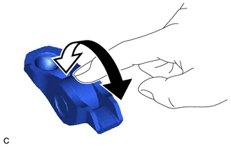
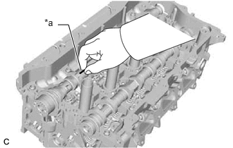
- INSPECT NO. 1 VALVE ROCKER ARM SUB-ASSEMBLY
- INSPECT VALVE LASH ADJUSTER ASSEMBLY NOTE:
- Keep the valve lash adjuster assembly free from dirt and foreign matter.
- Only use clean engine oil.
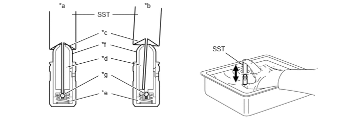
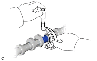
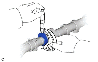
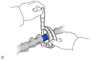
- Place the valve lash adjuster assembly into a container filled with engine oil.
- Insert the tip of SST into the valve lash adjuster assembly plunger and use the tip to press down on the check ball inside the plunger.
*a Correct *b Incorrect *c Tapered Path *d Low Pressure Chamber *e High Pressure Chamber *f Plunger *g Check Ball - - - SST: 09276-75010
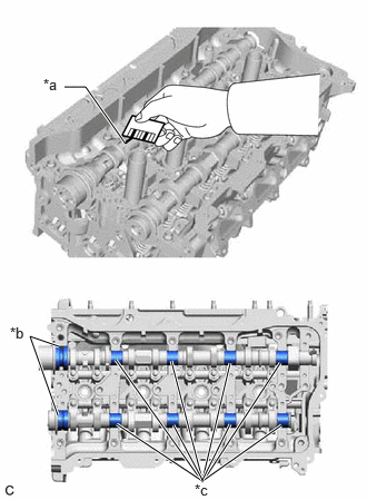
- Squeeze SST and the valve lash adjuster assembly together to move the plunger up and down 5 to 6 times.
- Check the movement of the plunger and bleed the air.
OK
Plunger moves up and down.
NOTE:When bleeding air from the high-pressure chamber, make sure that the tip of SST is pressing the check ball as shown in the illustration. If the check ball is not pressed, air will not bleed.
- After bleeding the air, remove SST. Then try to quickly and firmly press the plunger by hand.
OK
The plunger is very difficult to move.
HINT:
If the plunger is easy to move, replace the valve lash adjuster assembly.
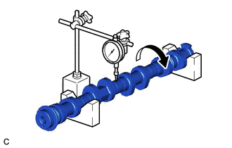
- INSPECT CAMSHAFT
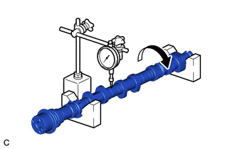
- Inspect the camshaft for runout.
- Place the camshaft on V-blocks.
- Using a dial indicator, measure the runout at the center journal.
Maximum Runout
0.03 mm (0.00118 in.)
HINT:
- If the runout is more than the maximum, replace the camshaft.
- Check the camshaft oil clearance after replacing the camshaft.
- Inspect the cam lobes.
- Using a micrometer, measure the cam lobe height.
Standard Cam Lobe Height
42.217 to 42.417 mm (1.66208 to 1.66996 in.)
Minimum Cam Lobe Height
42.157 mm (1.65972 in.)
HINT:
If the cam lobe height is less than the minimum, replace the camshaft.
- Using a micrometer, measure the cam lobe height.
- Inspect the camshaft journals.
- Using a micrometer, measure the journal diameter.
Standard Journal Diameter
Item Specified Condition No. 1 journal 33.984 to 34.000 mm (1.33795 to 1.33858 in.) Other journals 23.959 to 23.975 mm (0.94327 to 0.94390 in.) HINT:
If the journal diameter is not as specified, check the camshaft oil clearance.
See step 5
- Using a micrometer, measure the journal diameter.
- Inspect the camshaft for runout.
- INSPECT NO. 2 CAMSHAFT
- Inspect the No. 2 camshaft for runout.
- Place the No. 2 camshaft on V-blocks.
- Using a dial indicator, measure the runout at the center journal.
Maximum Runout
0.03 mm (0.00118 in.)
HINT:
- If the runout is more than the maximum, replace the No. 2 camshaft.
- Check the camshaft oil clearance after replacing the No. 2 camshaft.
- Inspect the cam lobes.
- Using a micrometer, measure the cam lobe height.
Standard Cam Lobe Height
Item Specified Condition No. 2 camshaft 37.914 to 38.114 mm (1.49267 to 1.50055 in.) No. 2 camshaft (for Fuel Pump) 39.398 to 39.598 mm (1.55110 to 1.55897 in.) Minimum Cam Lobe Height
Item Specified Condition No. 2 camshaft 37.804 mm (1.48834 in.) No. 2 camshaft (for Fuel Pump) 39.348 mm (1.54913 in.) HINT:
If the cam lobe height is less than the minimum, replace the No. 2 camshaft.
- Using a micrometer, measure the cam lobe height.
- Inspect the No. 2 camshaft journals.
- Using a micrometer, measure the journal diameter.
Standard Journal Diameter
Item Specified Condition No. 1 journal 40.984 to 41.000 mm (1.61354 to 1.61417 in.) Other journals 23.959 to 23.975 mm (0.94327 to 0.94390 in.) HINT:
If the journal diameter is not as specified, check the camshaft oil clearance.
See step 5
- Using a micrometer, measure the journal diameter.
- Inspect the No. 2 camshaft for runout.
- INSPECT CAMSHAFT OIL CLEARANCE
- Clean the No. 1 camshaft bearing cap, No. 2 camshaft bearing cap, 2 No. 3 camshaft bearing caps, No. 4 camshaft bearing cap, camshaft housing sub-assembly and camshaft journals.
- Place the camshaft and No. 2 camshaft on the camshaft housing sub-assembly.
- Lay a strip of Plastigage across each of the camshaft journals.
*a Plastigage - Install the camshaft bearing caps.
Refer to PROCEDURE - Step 23 [12/2019 - 10/2021] , or refer to PROCEDURE - Step 23 [10/2021 - 11/2023] , or refer to PROCEDURE - Step 23 [11/2023 - ]
NOTE:Do not turn the camshafts.
- Remove the camshaft bearing caps.
See step 44 [12/2019 - 11/2023], or see step 44 [11/2023 - ]
- Measure the Plastigage at its widest point.
Standard Oil Clearance (for Camshaft)
Item Specified Condition No. 1 journal 0.035 to 0.072 mm (0.00138 to 0.00283 in.) Other journals 0.025 to 0.062 mm (0.000984 to 0.00244 in.) Standard Oil Clearance (for No. 2 camshaft)
Item Specified Condition No. 1 journal 0.027 to 0.064 mm (0.00106 to 0.00252 in.) Other journals 0.025 to 0.062 mm (0.000984 to 0.00244 in.) Maximum Oil Clearance (for Camshaft)
Item Specified Condition No. 1 journal 0.085 mm (0.00335 in.) Other journals 0.085 mm (0.00335 in.) Maximum Oil Clearance (for No. 2 camshaft)
Item Specified Condition No. 1 journal 0.085 mm (0.00335 in.) Other journals 0.085 mm (0.00335 in.) *a Plastigage *b No. 1 Journal *c Other Journal NOTE:Completely remove the Plastigage after the inspection.
HINT:
If the oil clearance is more than the maximum, replace the camshaft or No. 2 camshaft. If necessary, replace the camshaft housing sub-assembly.
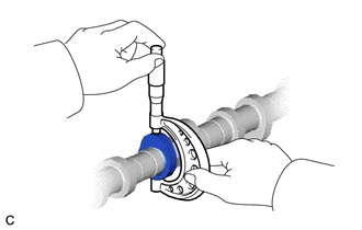
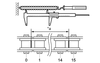
- INSPECT CHAIN SUB-ASSEMBLY
- Using a spring scale, pull the chain sub-assembly with a force of 147 N (15 kgf, 33.0 lbf) as shown in the illustration.
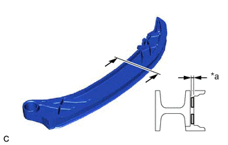
*a Measurement Length - Using a vernier caliper, measure the length of 15 links.
Maximum Chain Elongation
116.35 mm (4.58 in.)
NOTE:Perform the measurement at 3 random places. Use the average of the measurements.
HINT:
If the average elongation is more than the maximum, replace the chain sub-assembly.
- Using a spring scale, pull the chain sub-assembly with a force of 147 N (15 kgf, 33.0 lbf) as shown in the illustration.
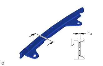
- INSPECT OIL PUMP DRIVE CHAIN SUB-ASSEMBLY
*a Measurement Length Using a spring scale, pull the oil pump drive chain sub-assembly with a force of 147 N (15 kgf, 33.0 lbf) as shown in the illustration.
- Using a vernier caliper, measure the length of 15 links.
Maximum Chain Elongation
116.35 mm (4.58 in.)
NOTE:Perform the measurement at 3 random places. Use the average of the measurements.
HINT:
If the average elongation is more than the maximum, replace the oil pump drive chain sub-assembly.
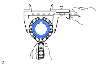
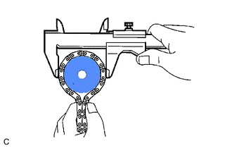
- INSPECT OIL PUMP DRIVE SPROCKET
- Place the oil pump drive chain sub-assembly around the oil pump drive sprocket.
- Using a vernier caliper, measure the diameter of the oil pump drive sprocket and oil pump drive chain sub-assembly.
Minimum Sprocket Diameter (with Oil Pump Drive Chain Sub-assembly)
51.23 mm (2.02 in.)
NOTE:The vernier caliper must be in contact with the chain rollers when measuring.
HINT:
If the diameter is less than the minimum, replace the oil pump drive chain sub-assembly and oil pump drive sprocket.
- Place the oil pump drive chain sub-assembly around the oil pump drive sprocket.
- INSPECT OIL PUMP DRIVE SHAFT SPROCKET
- Place the oil pump drive chain sub-assembly around the oil pump drive shaft sprocket.
- Using a vernier caliper, measure the diameter of the oil pump drive shaft sprocket and oil pump drive chain sub-assembly.
Minimum Sprocket Diameter (with Oil Pump Drive Chain Sub-assembly)
51.23 mm (2.02 in.)
NOTE:The vernier caliper must be in contact with the chain rollers when measuring.
HINT:
If the diameter is less than the minimum, replace the oil pump drive chain sub-assembly and oil pump drive shaft sprocket.
- Place the oil pump drive chain sub-assembly around the oil pump drive shaft sprocket.
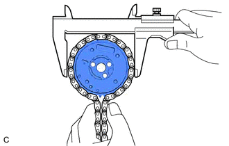
- INSPECT CAMSHAFT TIMING GEAR ASSEMBLY
- Place the chain sub-assembly around the camshaft timing gear assembly.
- Using a vernier caliper, measure the diameter of the camshaft timing gear assembly and chain sub-assembly.
Minimum Gear Diameter (with Chain Sub-assembly)
100.01 mm (3.94 in.)
NOTE:The vernier caliper must be in contact with the chain rollers when measuring.
HINT:
If the diameter is less than the minimum, replace the chain sub-assembly and camshaft timing gear assembly.
- Place the chain sub-assembly around the camshaft timing gear assembly.
- INSPECT CAMSHAFT TIMING EXHAUST GEAR ASSEMBLY
- Place the chain sub-assembly around the camshaft timing exhaust gear assembly.
- Using a vernier caliper, measure the diameter of the camshaft timing exhaust gear assembly and chain sub-assembly.
Minimum Gear Diameter (with Chain Sub-assembly)
100.01 mm (3.94 in.)
NOTE:The vernier caliper must be in contact with the chain rollers when measuring.
HINT:
If the diameter is less than the minimum, replace the chain sub-assembly and camshaft timing exhaust gear assembly.
- Place the chain sub-assembly around the camshaft timing exhaust gear assembly.
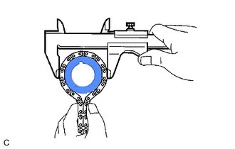
- INSPECT CRANKSHAFT TIMING SPROCKET
- Place the chain sub-assembly around the crankshaft timing sprocket.
- Using a vernier caliper, measure the diameter of the crankshaft timing sprocket and chain sub-assembly.
Minimum Sprocket Diameter (with Chain Sub-assembly)
51.23 mm (2.02 in.)
NOTE:The vernier caliper must be in contact with the chain rollers when measuring.
HINT:
If the diameter is less than the minimum, replace the chain sub-assembly and crankshaft timing sprocket.
- Place the chain sub-assembly around the crankshaft timing sprocket.
- INSPECT NO. 1 CHAIN TENSIONER ASSEMBLY
- INSPECT CHAIN TENSIONER SLIPPER
- INSPECT NO. 1 CHAIN VIBRATION DAMPER
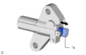
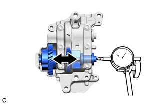
- INSPECT NO. 1 BALANCE SHAFT THRUST CLEARANCE
- Using a dial indicator, measure the thrust clearance while moving the No. 1 balance shaft back and forth.
Standard Thrust Clearance
0.05 to 0.09 mm (0.00197 to 0.00354 in.)
Maximum Thrust Clearance
0.09 mm (0.00354 in.)
HINT:
If the thrust clearance is more than the maximum, replace the engine balancer assembly.
- Using a dial indicator, measure the thrust clearance while moving the No. 1 balance shaft back and forth.
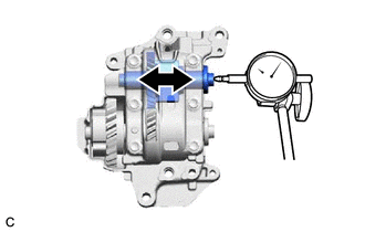
- INSPECT NO. 2 BALANCE SHAFT THRUST CLEARANCE
- Using a dial indicator, measure the thrust clearance while moving the No. 2 balance shaft back and forth.
Standard Thrust Clearance
0.05 to 0.09 mm (0.00197 to 0.00354 in.)
Maximum Thrust Clearance
0.09 mm (0.00354 in.)
HINT:
If the thrust clearance is more than the maximum, replace the engine balancer assembly.
- Using a dial indicator, measure the thrust clearance while moving the No. 2 balance shaft back and forth.
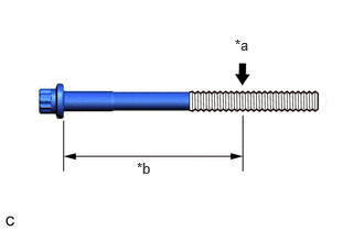
- INSPECT CYLINDER HEAD SET BOLT
- For 140 mm cylinder head set bolt:
- Using a vernier caliper, measure the diameter of the threads at the measurement point.
*a Measurement Point *b 105 mm Standard Diameter
10.7 to 10.9 mm (0.421 to 0.429 in.)
Minimum Diameter
10.6 mm (0.417 in.)
Measurement Point (Distance from the Seat)
105 mm (4.13 in.)
HINT:
- If the diameter is less than the minimum, replace the cylinder head set bolt with a new one. Failure to do so may lead to engine damage.
- If there is any thread deformation, replace the cylinder head set bolt with a new one.
- Using a vernier caliper, measure the diameter of the threads at the measurement point.
- For 150 mm cylinder head set bolt:
- Using a vernier caliper, measure the diameter of the threads at the measurement point.
*a Measurement Point *b 115 mm Standard Diameter
11.7 to 11.9 mm (0.461 to 0.469 in.)
Minimum Diameter
11.6 mm (0.457 in.)
Measurement Point (Distance from the Seat)
115 mm (4.53 in.)
HINT:
- If the diameter is less than the minimum, replace the cylinder head set bolt with a new one. Failure to do so may lead to engine damage.
- If there is any thread deformation, replace the cylinder head set bolt with a new one.
- Using a vernier caliper, measure the diameter of the threads at the measurement point.
- For 140 mm cylinder head set bolt:
- INSPECT EXHAUST MANIFOLD (TWC: Front Catalyst)
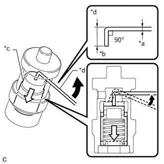
- INSPECT OIL NOZZLE VALVE SUB-ASSEMBLY
- Using a piece of wire, check that the check valve is not stuck.
*a 1 mm (0.0394 in.) *b 5 mm (0.197 in.) *c Check Valve *d Wire 
Move the wire in this direction. 
Movement of Check Valve HINT:
- Form a 1.0 mm (0.0394 in.) diameter piece of wire to the shape shown in the illustration.
- If the check valve is stuck, replace the oil nozzle valve sub-assembly with a new one.
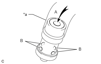
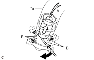
*a Hose Connect a hose to the oil nozzle valve sub-assembly.
- Check that air does not leak from the port (B) when blowing air into the port (A).
HINT:
If air leaks from the port (B), replace the oil nozzle valve sub-assembly with a new one.
- With the check valve depressed using a piece of wire, check that air flows from the port (B) when blowing air into the port (A).
*a Hose Move the wire in this direction. Movement of Check Valve HINT:
If air does not flow from the port (B), replace the oil nozzle valve sub-assembly with a new one.
- Disconnect the hose from the oil nozzle valve sub-assembly.
- Using a piece of wire, check that the check valve is not stuck.