Reassembly [11/2023 - ]: Procedure
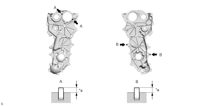
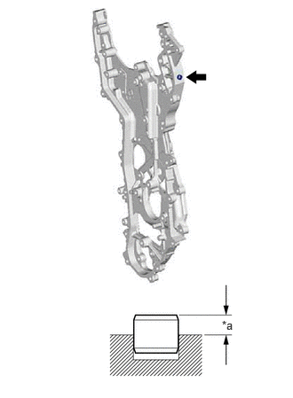
- INSTALL STRAIGHT PIN NOTE:
It is not necessary to remove the straight pins unless they are being replaced.
- No. 2 timing chain cover assembly side:
- Timing chain cover assembly side:
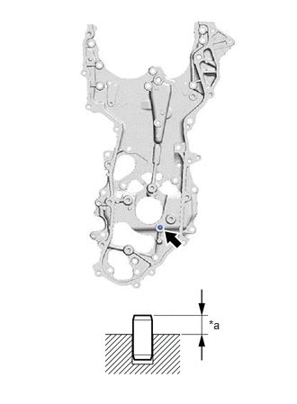
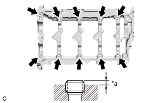
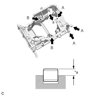
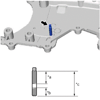
- INSTALL RING PIN NOTE:
It is not necessary to remove the ring pins unless they are being replaced.
- Camshaft housing sub-assembly side:
- Stiffening crankcase assembly side:
- Timing chain cover assembly side:
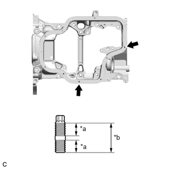
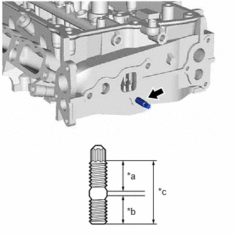
- INSTALL STUD BOLT NOTE:
If a stud bolt is deformed or its threads are damaged, replace it.
- Stiffening crankcase assembly side:
- Timing chain cover assembly side:
- w/ Stud Bolt:
- INSTALL WIRE HARNESS CLAMP BRACKET
- Stiffening crankcase assembly side:
- Camshaft housing sub-assembly side:
- Cylinder block sub-assembly side:
- INSTALL STRAIGHT SCREW PLUG
- INSTALL ENGINE BALANCER ASSEMBLY
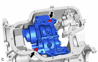
- INSTALL STIFFENING CRANKCASE ASSEMBLY
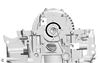
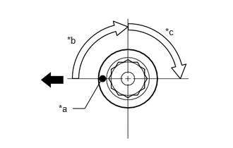
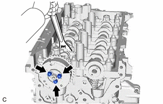
- Rotate the crankshaft clockwise so that the crankshaft timing gear key groove is at the position 270° from the bottom as shown in the illustration.
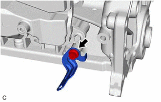
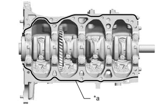
*a 270° *b Crankshaft Timing Gear Key Groove - Apply seal packing in a continuous line as shown in the illustration.
*a Seal Packing Seal Packing
Toyota Genuine Seal Packing Black, Three Bond 1207B or equivalent
Standard Seal Packing Dimension
Area Specified Condition Continuous Line Diameter 2.5 to 3.5 mm (0.0984 to 0.138 in.) NOTE:- Remove any oil from the contact surfaces.
- Install the stiffening crankcase assembly within 3 minutes and tighten the bolts within 10 minutes of applying seal packing.
- Do not add engine oil for at least 2 hours after the installation.
- Make sure that the diameter at the start and end of each line of seal packing is 5 +/- 2 mm (0.197 +/- 0.0787 in.).
- Do not start the engine for at least 2 hours after installation.
- After installation, if the seal packing has seeped out, wipe it off.
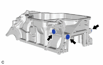
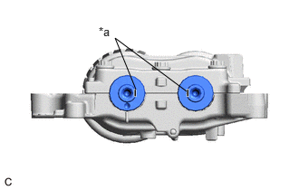
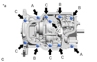
- Check that the front cutouts are as shown in the illustration.
*a Cutout - Clean the bolts and bolt holes.
- Temporarily install the stiffening crankcase assembly with the 11 bolts.
Bolt Length
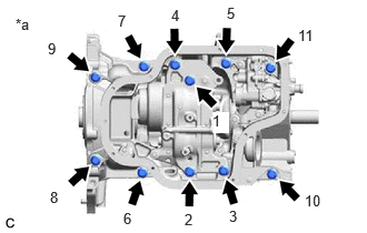
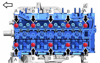
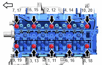
Item Length Bolt (A) 40 mm (1.57 in.) Bolt (B) 90 mm (3.54 in.) Bolt (C) 170 mm (6.69 in.) *a Bolt Type - Tighten the 11 bolts in the order shown in the illustration to install the stiffening crankcase assembly.
*a Tightening Order Torque: 43 N.m (438 kgf/cm, 32 ft.lbf)
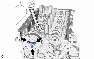
- Rotate the crankshaft clockwise so that the crankshaft timing gear key groove is at the position 270° from the bottom as shown in the illustration.
- INSTALL OIL PUMP ASSEMBLY
Refer to PROCEDURE - Step 3
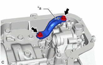
- INSTALL OIL PUMP BRACKET
- INSTALL ENGINE OIL LEVEL SENSOR
Refer to PROCEDURE - Step 1
- INSTALL OIL STRAINER SUB-ASSEMBLY
- INSTALL NO. 2 OIL PAN SUB-ASSEMBLY
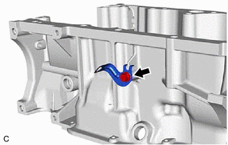
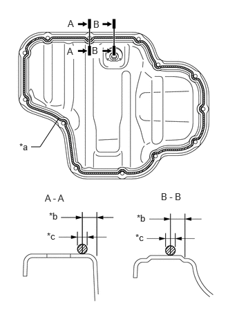
- Apply seal packing in a continuous line as shown in the illustration.
*a Seal Packing *b 4.5 mm (0.177 in.) *c 2.5 to 3.5 mm (0.0984 to 0.138 in.) Seal Packing
Toyota Genuine Seal Packing Black, Three Bond 1207B or equivalent
Standard Seal Packing Diameter
2.5 to 3.5 mm (0.0984 to 0.138 in.)
NOTE:- Remove any oil from the contact surfaces.
- Install the No. 2 oil pan sub-assembly within 3 minutes and tighten the bolts and nuts within 10 minutes of applying seal packing.
- Do not start the engine for at least 2 hours after installation.
- Make sure that the diameter at the start and end of each line of seal packing is 5 +/- 2 mm (0.197 +/- 0.0787 in.).
- Do not add engine oil for at least 2 hours after the installation.
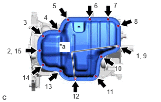
- Install the No. 2 oil pan sub-assembly with the 11 bolts and 2 nuts in several steps in the order shown in the illustration.
*a Nut Torque: 10 N.m (102 kgf/cm, 7 ft.lbf)
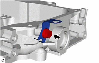
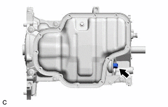
- Apply seal packing in a continuous line as shown in the illustration.
- INSTALL OIL PAN DRAIN PLUG
- Install a new gasket and the oil pan drain plug to the No. 2 oil pan sub-assembly.
Torque: 40 N.m (408 kgf/cm, 30 ft.lbf)
- Install a new gasket and the oil pan drain plug to the No. 2 oil pan sub-assembly.
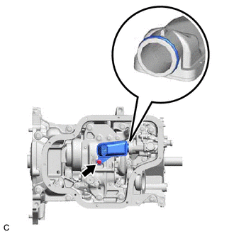
- INSTALL OIL FILTER UNION
- INSTALL OIL FILTER SUB-ASSEMBLY
Refer to PROCEDURE - Step 4
- INSTALL REAR ENGINE OIL SEAL
Refer to PROCEDURE - Step 1
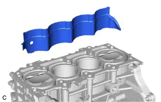
- INSTALL CYLINDER BLOCK WATER JACKET SPACER
- INSTALL CYLINDER HEAD GASKET
Refer to PROCEDURE - Step 1
- INSTALL CYLINDER HEAD SUB-ASSEMBLY
HINT:
The cylinder head set bolts are tightened in 3 progressive steps.
- Place the cylinder head sub-assembly on the cylinder block sub-assembly.NOTE:
- Ensure that the contact surface of the cylinder head sub-assembly is free of oil.
- Place the cylinder head sub-assembly on the cylinder block sub-assembly gently in order not to damage the cylinder head gasket with the bottom of the cylinder head sub-assembly.
- Do not allow oil to adhere to the bottom of the cylinder head sub-assembly.
- Clean the bolt and bolt hole.
- Apply a light coat of engine oil to the threads and under the heads of the cylinder head set bolts.
- Install the 10 plate washers to the 10 cylinder head set bolts.
Bolt Length
Item Length Bolt (A) 139.1 to 140.9 mm (5.48 to 5.55 in.) Bolt (B) 149.1 to 150.9 mm (5.87 to 5.94 in.) 
Front of Engine - Step 1:
- Step 2:
- Step 3:
- Tighten the cylinder head set bolts another 90° in the order shown in step 1.
- Check that the paint marks are now facing rearward.
HINT:
Perform "Inspection After Repair" after replacing the cylinder head sub-assembly.
Refer to INITIALIZATION [10/2021 - ]
- Place the cylinder head sub-assembly on the cylinder block sub-assembly.
- INSTALL WATER BY-PASS PIPE SUB-ASSEMBLY
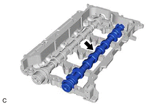
- INSTALL NO. 2 CAMSHAFT
HINT:
Perform "Inspection After Repair" after replacing the No. 2 camshaft.
Refer to INITIALIZATION [10/2021 - ]
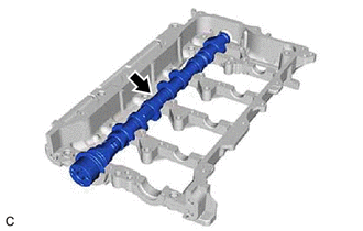
- INSTALL CAMSHAFT
HINT:
Perform "Inspection After Repair" after replacing the camshaft.
Refer to INITIALIZATION [10/2021 - ]
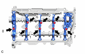
- INSTALL CAMSHAFT BEARING CAP
- Place the No. 1 camshaft bearing cap, No. 2 camshaft bearing cap and 2 No. 3 camshaft bearing caps and No. 4 camshaft bearing cap in their correct locations.
- Uniformly tighten the 8 bolts in the order shown in the illustration.
Torque: 16 N.m (163 kgf/cm, 12 ft.lbf)
- Check the torque of each bolt again.
- Check that the camshaft and No. 2 camshaft turns smoothly.
- Place the No. 1 camshaft bearing cap, No. 2 camshaft bearing cap and 2 No. 3 camshaft bearing caps and No. 4 camshaft bearing cap in their correct locations.
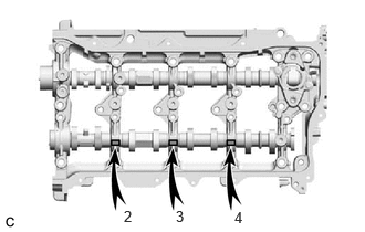
- INSTALL VALVE STEM CAP
- INSTALL VALVE LASH ADJUSTER ASSEMBLY
- Inspect the 16 valve lash adjuster assemblies before installing them.
Refer to PROCEDURE - Step 2
- Install the 16 valve lash adjuster assemblies to the cylinder head sub-assembly.NOTE:
Install the same parts in the same combination to their original locations.
- Inspect the 16 valve lash adjuster assemblies before installing them.
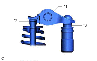
- INSTALL NO. 1 VALVE ROCKER ARM SUB-ASSEMBLY
- Apply engine oil to the valve lash adjuster assembly tips and valve stem caps.
*1 No. 1 Valve Rocker Arm Sub-assembly *2 Valve Stem Cap *3 Valve Lash Adjuster Assembly - Install the 16 No. 1 valve rocker arm sub-assemblies as shown in the illustration.NOTE:
Install the same parts in the same combination to their original locations.
- Apply engine oil to the valve lash adjuster assembly tips and valve stem caps.
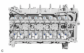
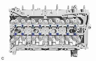
- INSTALL CAMSHAFT HOUSING SUB-ASSEMBLY
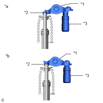
- Check that the No. 1 valve rocker arm sub-assemblies are installed as shown in the illustration.
*1 No. 1 Valve Rocker Arm Sub-assembly *2 Valve Stem Cap *3 Valve Lash Adjuster Assembly *a Incorrect *b Correct - Apply seal packing in a continuous line as shown in the illustration.
Seal Packing
Toyota Genuine Seal Packing Black, Three Bond 1207B or equivalent
Standard Seal Packing Diameter
3.0 to 4.0 mm (0.118 to 0.157 in.)
*a Seal Packing NOTE:- Remove any oil from the contact surfaces.
- Install the camshaft housing sub-assembly within 3 minutes and tighten the bolts within 10 minutes of applying seal packing.
- Do not start the engine for at least 2 hours after installation.
- Make sure that the diameter at the start and end of each line of seal packing is 5 +/- 2 mm (0.197 +/- 0.0787 in.).
- Do not add engine oil for at least 2 hours after installation.
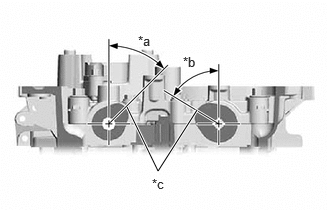
- Position the camshaft and No. 2 camshaft as shown in the illustration.
*a 28° to 58° *b 43° to 73° *c No. 1 Cylinder Cam Nose - Temporarily install the camshaft housing sub-assembly with the 18 bolts.
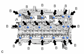
Bolt Length
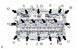
Item Length Bolt (A) 40 mm (1.57 in.) Bolt (B) 65 mm (2.56 in.) - Tighten the 18 bolts in several steps in the order shown in the illustration.
Torque: 28.5 N.m (291 kgf/cm, 21 ft.lbf)
NOTE:After installation, if the seal packing has seeped out, wipe it off.
- Check that the No. 1 valve rocker arm sub-assemblies are installed as shown in the illustration.
- INSTALL FUEL PUMP LIFTER GUIDE
- INSTALL CRANKSHAFT TIMING GEAR KEY
- INSTALL OIL NOZZLE VALVE SUB-ASSEMBLY
- INSTALL TIMING CHAIN COVER ASSEMBLY
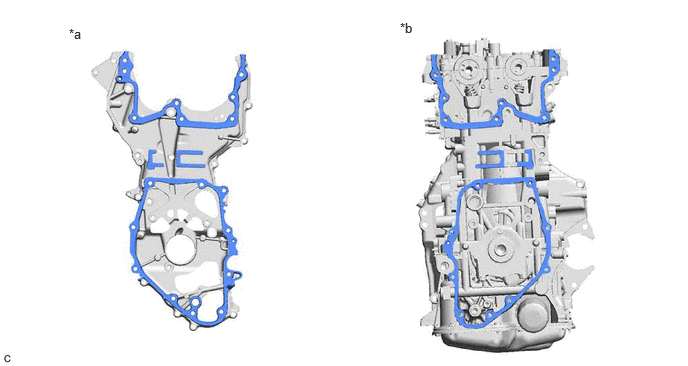
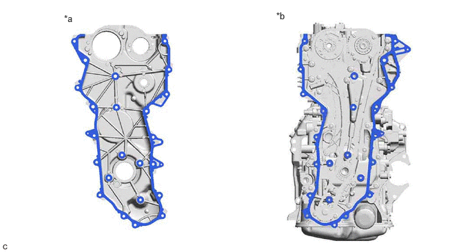
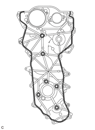
- Clean the contact surfaces of the timing chain cover assembly, cylinder head sub-assembly, camshaft housing sub-assembly, cylinder block sub-assembly, oil pump assembly and stiffening crankcase assembly, and confirm that no oil, moisture, or other foreign matter is on the surfaces.
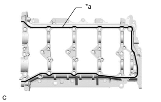
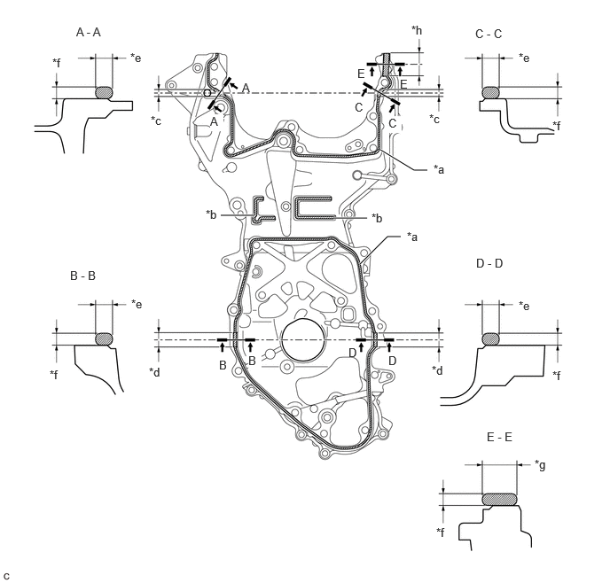
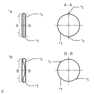
*a Timing Chain Cover Assembly Side *b Engine Assembly Side - Apply seal packing to the timing chain cover assembly as shown in the illustration.
*a 2.5 to 3.5 mm (0.0984 to 0.138 in.) *b 2.0 to 6.0 mm (0.0787 to 0.236 in.) *c 10 mm (0.394 in.) *d 20 mm (0.787 in.) *e 4.0 to 6.0 mm (0.157 to 0.236 in.) *f 3.0 to 4.0 mm (0.118 to 0.157 in.) *g 8.0 to 10 mm (0.315 to 0.394 in.) *h 30 mm (1.18 in.) 
Seal Packing - - Seal Packing
Toyota Genuine Seal Packing Black, Three Bond 1207B or equivalent
NOTE:- Clean the surfaces with non-residue solvent before applying seal packing.
- Install the timing chain cover assembly within 3 minutes and tighten the bolts within 10 minutes of applying seal packing.
- Do not add engine oil for at least 2 hours after installation.
- Do not start the engine for at least 2 hours after installation.
- Make sure that the diameter at the start and end of each line of seal packing is 5 +/- 2 mm (0.197 +/- 0.0787 in.).
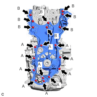
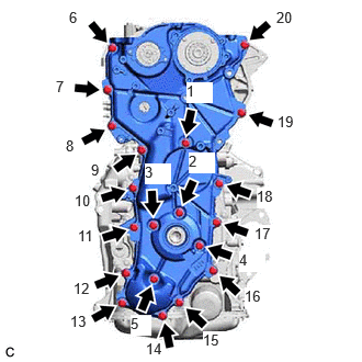
- Temporarily install the timing chain cover assembly with the 19 bolts.
Bolt Length
Bolt Length Width Across Flats (A) 30 mm (1.18 in.) 12 mm (0.472 in.) (B) 45 mm (1.77 in.) 12 mm (0.472 in.) NOTE:Make sure there is no oil on the bolts. If oil is found on any bolt, clean it before installation.
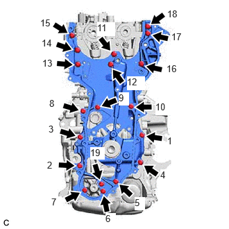
- Tighten the 19 bolts in the order shown in the illustration.
Torque: 27 N.m (275 kgf/cm, 20 ft.lbf)
- Clean the contact surfaces of the timing chain cover assembly, cylinder head sub-assembly, camshaft housing sub-assembly, cylinder block sub-assembly, oil pump assembly and stiffening crankcase assembly, and confirm that no oil, moisture, or other foreign matter is on the surfaces.
- INSTALL CAMSHAFT TIMING EXHAUST GEAR ASSEMBLY
HINT:
Perform "Inspection After Repair" after replacing the camshaft timing exhaust gear assembly.
Refer to INITIALIZATION [10/2021 - ]
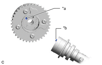
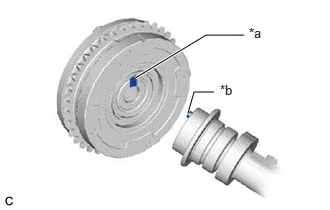
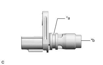
- Align and fit the knock pin of the No. 2 camshaft to the knock pin hole of the camshaft timing exhaust gear assembly.
*a Knock Pin Hole *b Knock Pin - Type A:
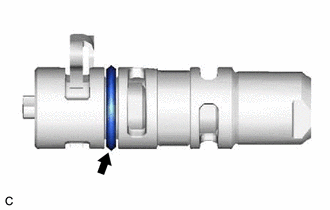
- Apply a light coat of engine oil to the O-ring of the camshaft timing oil control valve assembly (exhaust camshaft timing gear bolt assembly).NOTE:
If reusing the camshaft timing oil control valve assembly (exhaust camshaft timing gear bolt assembly), be sure to inspect the O-ring.
- Using a wrench, hold the hexagonal portion of the No. 2 camshaft.NOTE:
Be careful not to damage the camshaft housing sub-assembly, cylinder head sub-assembly and spark plug tube with the wrench.
- Using a 5 mm hexagon socket wrench, install the camshaft timing exhaust gear assembly and camshaft timing oil control valve assembly (exhaust camshaft timing gear bolt assembly) with the 3 bolts.
Torque: 19 N.m (194 kgf/cm, 14 ft.lbf)
- Apply a light coat of engine oil to the O-ring of the camshaft timing oil control valve assembly (exhaust camshaft timing gear bolt assembly).
- Type B:
- Using a wrench, hold the hexagonal portion of the No. 2 camshaft.NOTE:
Be careful not to damage the camshaft housing sub-assembly, cylinder head sub-assembly and spark plug tube with the wrench.
- Using a 5 mm hexagon socket wrench, install the camshaft timing exhaust gear assembly and camshaft timing oil control valve assembly (exhaust camshaft timing gear bolt assembly) with the 3 bolts.
Torque: 19 N.m (194 kgf/cm, 14 ft.lbf)
NOTE:Make sure to fit the protrusion of the camshaft timing oil control valve assembly (exhaust camshaft timing gear bolt assembly) into the cutout of the camshaft timing exhaust gear assembly.
- Pull the camshaft timing oil control valve assembly (exhaust camshaft timing gear bolt assembly) to confirm that is installed securely.
- Using a wrench, hold the hexagonal portion of the No. 2 camshaft.
- Align and fit the knock pin of the No. 2 camshaft to the knock pin hole of the camshaft timing exhaust gear assembly.
- SET NO. 1 CYLINDER TO TDC (COMPRESSION)
- Temporarily install the crankshaft pulley bolt.
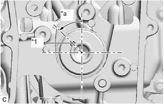
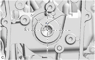
- Rotate the crankshaft 44.2° counterclockwise to position the crankshaft timing gear key as shown in the illustration.
*1 Crankshaft Timing Gear Key *a 44.2° - Check that the timing marks of the camshaft timing exhaust gear assembly and knock pin are as shown in the illustration.
*a Timing Mark *b Knock Pin
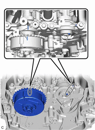
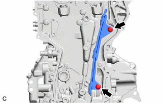
- INSTALL NO. 1 CHAIN VIBRATION DAMPER
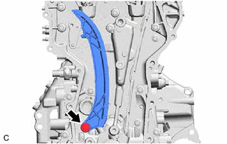
- INSTALL CHAIN TENSIONER SLIPPER
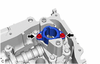
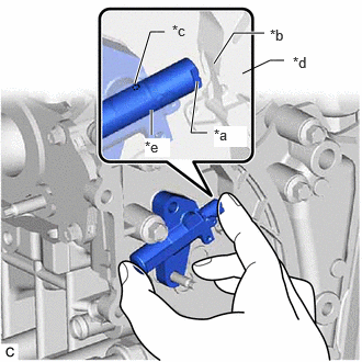
- INSTALL NO. 1 CHAIN TENSIONER ASSEMBLY
HINT:
After replacing or removing and installing the No. 1 chain tensioner assembly, an abnormal noise may occur at start up until the oil in the line has had time to replenish.
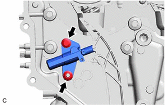
- While slightly pushing in the plunger of the No. 1 chain tensioner assembly, install the chain tensioner slipper.
*a End of the plunger *b Groove *c Oil Hole *d Chain Tensioner Slipper *e Plunger HINT:
- Make sure that the end of the plunger is correctly seated in the groove of the chain tensioner slipper.
- Make sure that the oil hole of the plunger is facing up.
- Using an 8 mm socket wrench, install the bolt.
Torque: 10 N.m (102 kgf/cm, 7 ft.lbf)
- Install the No. 1 chain tensioner assembly with the nut.
Torque: 10 N.m (102 kgf/cm, 7 ft.lbf)
- While slightly pushing in the plunger of the No. 1 chain tensioner assembly, install the chain tensioner slipper.
- INSTALL CHAIN SUB-ASSEMBLY
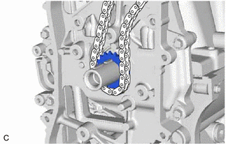
- Set the crankshaft timing gear key as shown in the illustration.
*1 Crankshaft Timing Gear Key - Remove the crankshaft pulley bolt.
- Install the crankshaft timing sprocket and chain sub-assembly.
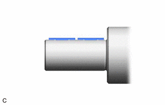
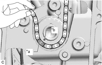
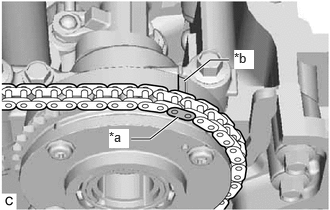
- Align the paint mark (yellow) of the chain sub-assembly with the timing mark of the crankshaft timing sprocket and install the chain sub-assembly to the crankshaft timing sprocket.
*a Paint Mark (Yellow) *b Timing Mark - Using the hexagonal portion of the No. 2 camshaft, rotate the No. 2 camshaft counterclockwise with a wrench, align the timing mark of the camshaft timing exhaust gear assembly with the paint mark (pink) of the chain sub-assembly, and install the chain sub-assembly to the camshaft timing exhaust gear assembly.
*a Paint Mark (Pink) *b Timing Mark 
Turn
- Set the crankshaft timing gear key as shown in the illustration.
- INSTALL CAMSHAFT TIMING GEAR ASSEMBLY
HINT:
Perform "Inspection After Repair" after replacing the camshaft timing gear assembly.
Refer to INITIALIZATION [10/2021 - ]
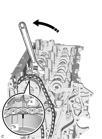
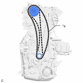
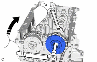
- Hold the hexagonal portion of the No. 2 camshaft with a wrench and turn the camshaft timing exhaust gear assembly clockwise to loosen the chain sub-assembly between the camshaft timing exhaust gear assembly and crankshaft timing sprocket as shown in the illustration.
*a Loosen - Align the paint mark (pink) of the chain sub-assembly and the timing mark of the camshaft timing gear assembly.
*a Paint Mark (Pink) *b Timing Mark - Align and fit the knock pin of the camshaft to the knock pin hole of the camshaft timing gear assembly.
*a Knock Pin Hole *b Knock Pin - Using a wrench, hold the hexagonal portion of the camshaft.NOTE:
- Be careful not to damage the camshaft housing sub-assembly, cylinder head sub-assembly and spark plug tube with the wrench.
- Do not disassemble the camshaft timing gear assembly.
*a Hold Turn - Using a 10 mm bi-hexagon socket wrench, install the camshaft timing gear assembly to the camshaft with the bolt.
Torque: 86 N.m (877 kgf/cm, 63 ft.lbf)
- Hold the hexagonal portion of the No. 2 camshaft with a wrench and turn the camshaft timing exhaust gear assembly clockwise to loosen the chain sub-assembly between the camshaft timing exhaust gear assembly and crankshaft timing sprocket as shown in the illustration.
- INSTALL OIL PUMP DRIVE CHAIN SUB-ASSEMBLY
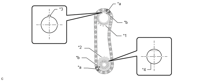
- Set the crankshaft timing gear key as shown in the illustration.
*1 Oil Pump Drive Sprocket *2 Oil Pump Drive Shaft Sprocket *3 Crankshaft Timing Gear Key *4 Oil Pump Assembly *a Mark Plate *b Timing Mark - Turn the oil pump drive shaft so that the flat face is facing upward.
- Align the mark plates with the timing marks of the oil pump drive sprocket and oil pump drive shaft sprocket as shown in the illustration.
HINT:
Make sure the mark plates of the oil pump drive chain sub-assembly are facing away from the engine assembly.
- With the oil pump drive chain sub-assembly placed around the oil pump drive sprocket and oil pump drive shaft sprocket, install the oil pump drive sprocket to the crankshaft and temporarily install the oil pump drive shaft sprocket to the oil pump drive shaft.
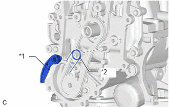
- Install the chain damper spring to the chain tensioner plate, and then install the chain tensioner plate.
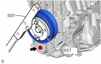
*1 Chain Tensioner Plate *2 Chain Damper Spring - Temporarily install the crankshaft pulley assembly with the crankshaft pulley bolt.
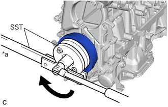
- Using SST, hold the crankshaft pulley assembly and install the bolt.
- SST: 09213-54015
- SST: 09330-00021
Torque: 50 N.m (510 kgf/cm, 37 ft.lbf)
- Remove SST, the crankshaft pulley bolt and crankshaft pulley assembly.
- Set the crankshaft timing gear key as shown in the illustration.
- SET NO. 1 CYLINDER TO TDC (COMPRESSION)
Refer to PROCEDURE - Step 31
- INSTALL NO. 2 TIMING CHAIN COVER ASSEMBLY
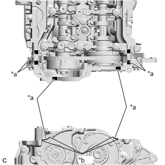
- Clean the contact surfaces of the No. 2 timing chain cover assembly and timing chain cover assembly, and confirm that no oil, moisture, or other foreign matter is on the surfaces.
*a No. 2 Timing Chain Cover Assembly Side *b Timing Chain Cover Assembly Side - Apply seal packing to the No. 2 timing chain cover assembly as shown in the illustration.
Seal Packing
Toyota Genuine Seal Packing Black, Three Bond 1207B or equivalent
Standard Seal Packing Diameter
2.5 to 3.5 mm (0.0984 to 0.138 in.)
NOTE:- Clean the surfaces with non-residue solvent before applying seal packing.
- Install the No. 2 timing chain cover assembly within 3 minutes and tighten the bolts within 10 minutes of applying seal packing.
- Do not add engine oil for at least 2 hours after installation.
- Do not start the engine for at least 2 hours after installation.
- Make sure that the diameter at the start and end of each line of seal packing is 5 +/- 2 mm (0.197 +/- 0.0787 in.).
Seal Packing - Temporarily install the No. 2 timing chain cover assembly to the timing chain cover assembly with the 20 bolts.NOTE:
Make sure there is no oil on the bolts. If oil is found on any bolt, clean it before installation.
- Tighten the 20 bolts in the order shown in the illustration.
Torque: 24 N.m (245 kgf/cm, 18 ft.lbf)
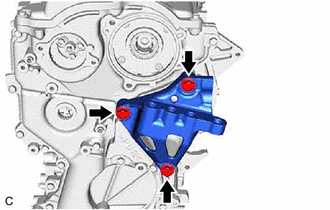
- Install the engine mounting bracket RH to the No. 2 timing chain cover assembly with the 3 bolts.
Torque: 43 N.m (438 kgf/cm, 32 ft.lbf)
NOTE:After applying seal packing to the No. 2 timing chain cover assembly, install the engine mounting bracket RH within 10 minutes.
- Clean the contact surfaces of the No. 2 timing chain cover assembly and timing chain cover assembly, and confirm that no oil, moisture, or other foreign matter is on the surfaces.
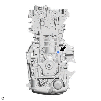
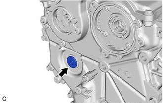
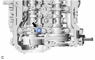
- INSTALL STRAIGHT SCREW PLUG
- Apply adhesive to the straight screw plug.
Adhesive
Toyota Genuine Adhesive 1324, Three Bond 1324 or equivalent
- Using a 10 mm hexagon wrench, install the straight screw plug to the No. 2 timing chain cover assembly.
Torque: 40 N.m (408 kgf/cm, 30 ft.lbf)
NOTE:- Install the straight screw plug within 3 minutes of applying adhesive.
- Do not add engine oil for at least 1 hour after installation.
- Apply adhesive to the straight screw plug.
- INSTALL TIMING CHAIN COVER OIL SEAL
Refer to PROCEDURE - Step 1
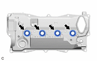
- INSTALL SPARK PLUG TUBE GASKET
- INSTALL CYLINDER HEAD COVER SUB-ASSEMBLY
- Apply a light coat of engine oil to a new camshaft bearing cap oil hole gasket.
- Install the camshaft bearing cap oil hole gasket to the No. 1 camshaft bearing cap.
- Install 7 new cylinder head cover gaskets to the cylinder head cover sub-assembly.
- Apply seal packing as shown in the illustration.
*a Seal Packing Diameter: 3.0 to 6.0 mm *b Mark 
Seal Packing Seal Packing
Toyota Genuine Seal Packing Black, Three Bond 1207B or equivalent
Standard Seal Packing Diameter
3.0 to 6.0 mm (0.118 to 0.236 in.)
NOTE:- Remove any oil from the contact surfaces.
- Install the cylinder head cover sub-assembly within 3 minutes and tighten the bolts within 10 minutes of applying seal packing.
- Do not start the engine for at least 2 hours after installation.
*a O-ring Groove *b Camshaft Position Sensor Tip Perform this procedure only when reusing the 2 camshaft position sensors (for Exhaust Side and for Intake Side).
- Clean the O-ring groove of the 2 camshaft position sensors (for Exhaust Side and for Intake Side).NOTE:
Make sure the O-ring groove is free of foreign matter.
- Install a new O-ring to the 2 camshaft position sensors (for Exhaust Side and for Intake Side).NOTE:
Set the O-ring on the tip of the 2 camshaft position sensors (for Exhaust Side and for Intake Side) and roll it into the O-ring groove with bare hands to install it.
- Check if the O-ring is twisted.
HINT:
Check the entire circumference of the seam of the O-ring for twisting.
*1 O-ring *a OK *b NG *c Seam
- Clean the O-ring groove of the 2 camshaft position sensors (for Exhaust Side and for Intake Side).
- Apply a light coat of engine oil to the O-ring of the camshaft position sensor.
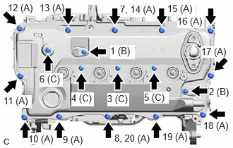
- Type A:
- Install the cylinder head cover sub-assembly with the 12 bolts (A) and using an 8 mm socket wrench, install 4 new bolts (C) and the 2 camshaft position sensors (for Exhaust Side and for Intake Side) with 2 new bolts (B) in the order shown in the illustration.
Bolt Length
Bolt Length Width Across Flats (A) 23.5 mm (0.925 in.) 10 mm (0.394 in.) (B), (C) 30 mm (1.18 in.) 8 mm (0.315 in.) Torque: 7.5 N.m (76 kgf/cm, 66 in.lbf)
NOTE:- If a camshaft position sensor (for Exhaust Side and for Intake Side) has been struck or dropped, replace it.
- Make sure that the 2 O-rings are not cracked or moved out of place when installing the 2 camshaft position sensors (for Exhaust Side and for Intake Side).
- Do not start the engine for at least 2 hours after installation.
- Do not add engine oil for at least 2 hours after installation.
HINT:
After tightening all bolts, check the tightening torque of the bolts (7) and (8). Retighten them if necessary.
- Install the cylinder head cover sub-assembly with the 12 bolts (A) and using an 8 mm socket wrench, install 4 new bolts (C) and the 2 camshaft position sensors (for Exhaust Side and for Intake Side) with 2 new bolts (B) in the order shown in the illustration.
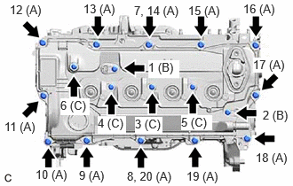
- Type B:
- Install the cylinder head cover sub-assembly with the 12 bolts (A) and using an 8 mm socket wrench, install 4 new bolts (C) and the 2 camshaft position sensors (for Exhaust Side and for Intake Side) with 2 new bolts (B) in the order shown in the illustration.
Bolt Length
Bolt Length Width Across Flats (A) 23.5 mm (0.925 in.) 10 mm (0.394 in.) (B), (C) 30 mm (1.18 in.) 8 mm (0.315 in.) Torque: 7.5 N.m (76 kgf/cm, 66 in.lbf)
NOTE:- If a camshaft position sensor (for Exhaust Side and for Intake Side) has been struck or dropped, replace it.
- Make sure that the 2 O-rings are not cracked or moved out of place when installing the 2 camshaft position sensors (for Exhaust Side and for Intake Side).
- Do not start the engine for at least 2 hours after installation.
- Do not add engine oil for at least 2 hours after installation.
HINT:
After tightening all bolts, check the tightening torque of the bolts (7) and (8). Retighten them if necessary.
- Install the cylinder head cover sub-assembly with the 12 bolts (A) and using an 8 mm socket wrench, install 4 new bolts (C) and the 2 camshaft position sensors (for Exhaust Side and for Intake Side) with 2 new bolts (B) in the order shown in the illustration.
- INSTALL WATER BY-PASS OUTLET
- INSTALL WATER OUTLET
- INSTALL CRANKSHAFT PULLEY ASSEMBLY
- INSTALL PCV VALVE (VENTILATION VALVE SUB-ASSEMBLY)
Refer to PROCEDURE - Step 1
- INSTALL CRANKSHAFT POSITION SENSOR
Refer to PROCEDURE - Step 1
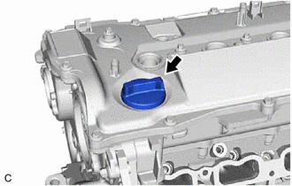
- INSTALL OIL FILLER CAP GASKET
- INSTALL OIL FILLER CAP SUB-ASSEMBLY
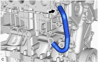
- INSTALL NO. 2 WATER BY-PASS HOSE
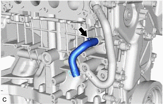
- INSTALL NO. 1 WATER BY-PASS HOSE
- INSTALL OIL COOLER ASSEMBLY
Refer to PROCEDURE - Step 1
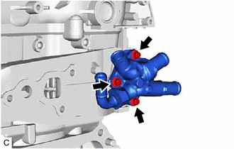
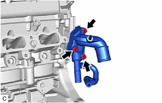
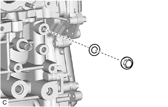
- INSTALL ENGINE WATER PUMP ASSEMBLY (WATER INLET HOUSING)
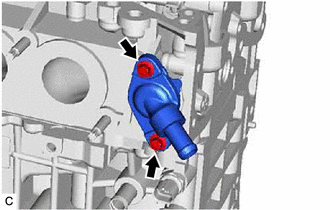
- Install the engine water pump assembly (water inlet housing) and a new gasket to the cylinder block sub-assembly with 4 bolts.
Torque: 43 N.m (438 kgf/cm, 32 ft.lbf)
- Install the engine water pump assembly (water inlet housing) and a new gasket to the cylinder block sub-assembly with 4 bolts.
- INSTALL WATER INLET WITH THERMOSTAT SUB-ASSEMBLY
Refer to PROCEDURE - Step 1
- INSTALL CAM TIMING CONTROL MOTOR O-RING
Refer to PROCEDURE - Step 1
- INSTALL CAM TIMING CONTROL MOTOR WITH EDU ASSEMBLY
Refer to PROCEDURE - Step 2
- INSTALL O-RING
Refer to PROCEDURE - Step 1
- INSTALL CAM TIMING OIL CONTROL SOLENOID ASSEMBLY
Refer to PROCEDURE - Step 2
- INSTALL OIL PRESSURE CONTROL VALVE ASSEMBLY
Refer to PROCEDURE - Step 1
- INSTALL OIL PRESSURE AND TEMPERATURE SENSOR
Refer to PROCEDURE - Step 1
- INSTALL STRAIGHT SCREW PLUG
- INSTALL ENGINE COOLANT TEMPERATURE SENSOR
Refer to PROCEDURE - Step 1
- INSTALL KNOCK CONTROL SENSOR
Refer to PROCEDURE - Step 1
- INSTALL SPARK PLUG
Refer to PROCEDURE - Step 1