Disassembly [11/2023 - ]: Procedure
- REMOVE SPARK PLUG
Refer to PROCEDURE - Step 3
- REMOVE KNOCK CONTROL SENSOR
Refer to PROCEDURE - Step 2
- REMOVE ENGINE COOLANT TEMPERATURE SENSOR
Refer to PROCEDURE - Step 4
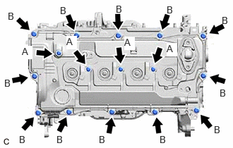
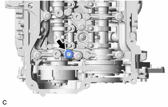
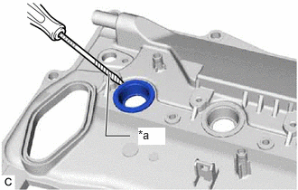
- REMOVE STRAIGHT SCREW PLUG
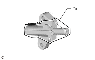
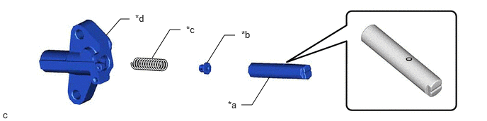
- REMOVE OIL PRESSURE AND TEMPERATURE SENSOR
Refer to PROCEDURE - Step 2
- REMOVE OIL PRESSURE CONTROL VALVE ASSEMBLY
Refer to PROCEDURE - Step 2
- REMOVE CAMSHAFT POSITION SENSOR (for Intake Side)
Refer to PROCEDURE - Step 2
- REMOVE CAMSHAFT POSITION SENSOR (for Exhaust Side)
Refer to PROCEDURE - Step 3
- REMOVE CAM TIMING OIL CONTROL SOLENOID ASSEMBLY
Refer to PROCEDURE - Step 3
- REMOVE O-RING
Refer to PROCEDURE - Step 4
- REMOVE CAM TIMING CONTROL MOTOR WITH EDU ASSEMBLY
Refer to PROCEDURE - Step 6
- REMOVE CAM TIMING CONTROL MOTOR O-RING
Refer to PROCEDURE - Step 7
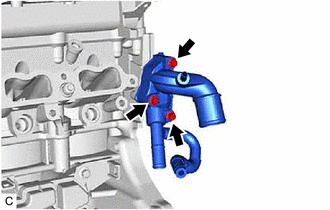
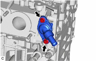
- REMOVE WATER INLET WITH THERMOSTAT SUB-ASSEMBLY
Refer to PROCEDURE - Step 3
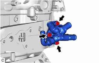
- REMOVE ENGINE WATER PUMP ASSEMBLY (WATER INLET HOUSING)
- REMOVE OIL COOLER ASSEMBLY
Refer to PROCEDURE - Step 4
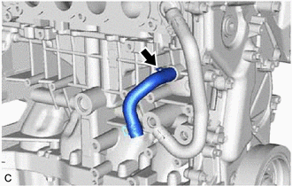
- REMOVE NO. 1 WATER BY-PASS HOSE
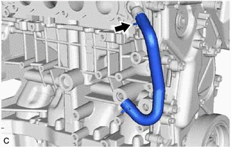
- REMOVE NO. 2 WATER BY-PASS HOSE
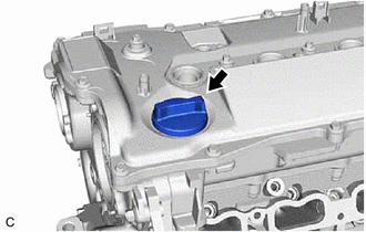
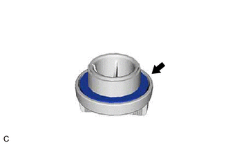
- REMOVE OIL FILLER CAP SUB-ASSEMBLY
- REMOVE OIL FILLER CAP GASKET
- REMOVE CRANKSHAFT POSITION SENSOR
Refer to PROCEDURE - Step 5
- REMOVE PCV VALVE (VENTILATION VALVE SUB-ASSEMBLY)
Refer to PROCEDURE - Step 2
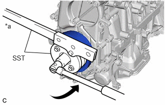
- REMOVE CRANKSHAFT PULLEY ASSEMBLY
- Using SST, hold the crankshaft pulley assembly and loosen the crankshaft pulley bolt. Further loosen the crankshaft pulley bolt until 2 or 3 threads remain screwed into the crankshaft.
*a Hold 
Turn - SST: 09213-54015
- SST: 09330-00021
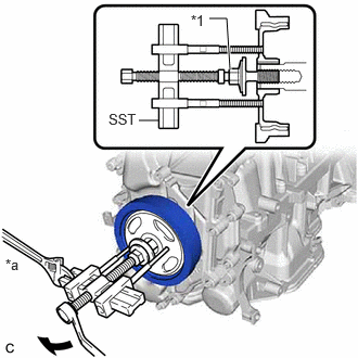
- Using SST and the crankshaft pulley bolt, remove the crankshaft pulley assembly and crankshaft pulley bolt.
*1 Crankshaft Pulley Bolt *a Hold Turn - SST: 09950-50013
- 09951-05010
- 09952-05010
- 09953-05020
- 09954-05070
- 09957-04010
HINT:
Apply lubricant to the threads and end of SST.
- SST: 09950-50013
- Using SST, hold the crankshaft pulley assembly and loosen the crankshaft pulley bolt. Further loosen the crankshaft pulley bolt until 2 or 3 threads remain screwed into the crankshaft.
- REMOVE WATER OUTLET
- REMOVE WATER BY-PASS OUTLET
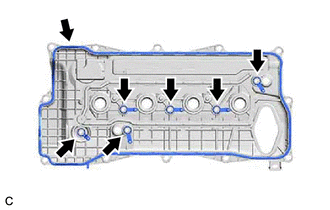
- REMOVE CYLINDER HEAD COVER SUB-ASSEMBLY
- REMOVE SPARK PLUG TUBE GASKET
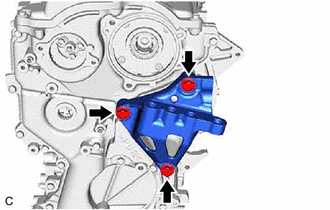
- REMOVE ENGINE MOUNTING BRACKET RH
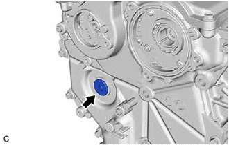
- REMOVE STRAIGHT SCREW PLUG
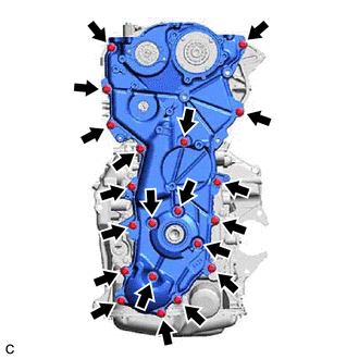
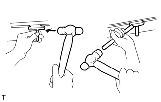
- REMOVE NO. 2 TIMING CHAIN COVER ASSEMBLY
- Remove the 20 bolts.
- Remove the No. 2 timing chain cover assembly from the timing chain cover assembly by prying the No. 2 timing chain cover assembly with a screwdriver with its tip wrapped with protective tape.
*a Protective Tape - - NOTE:Be careful not to damage the contact surfaces of the No. 2 timing chain cover assembly and timing chain cover assembly.
- Remove the 20 bolts.
- REMOVE TIMING CHAIN COVER OIL SEAL
- SET NO. 1 CYLINDER TO TDC (COMPRESSION)
- Temporarily install the crankshaft pulley bolt.
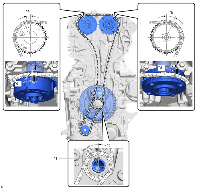
*1 Crankshaft Timing Gear Key - - *a Approximately 7.4° *b Approximately 27.3° *c Approximately 24.3° *d Timing Mark - Rotate the crankshaft clockwise and align the crankshaft timing gear key as shown in the illustration.
- Check that the timing marks on the camshaft timing exhaust gear assembly and camshaft timing gear assembly are as shown in the illustration.
- Remove the crankshaft pulley bolt.
HINT:
As the No. 2 camshaft may rotate counterclockwise strongly when the crankshaft pulley bolt is removed, use a wrench to hold the hexagonal portion of the No. 2 camshaft.
- Temporarily install the crankshaft pulley bolt.
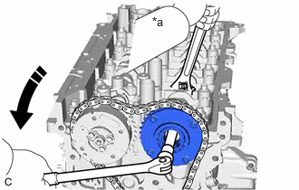
- REMOVE OIL PUMP DRIVE CHAIN SUB-ASSEMBLY
- Temporarily install the crankshaft pulley assembly with the crankshaft pulley bolt.
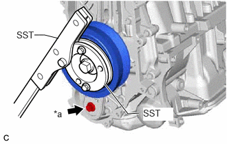
- Using SST, hold the crankshaft pulley assembly and remove the bolt.
*a Bolt - SST: 09213-54015
- SST: 09330-00021
- Remove SST, the crankshaft pulley bolt and crankshaft pulley assembly.
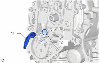
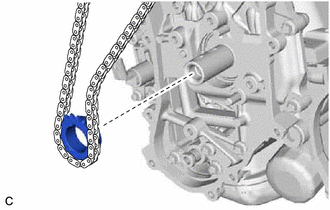
- Remove the chain tensioner plate and chain damper spring.
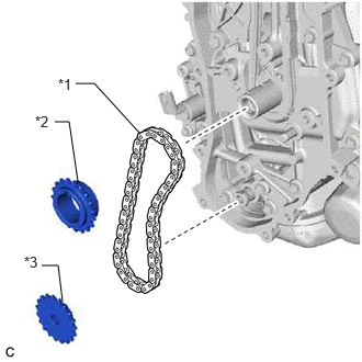
*1 Chain Tensioner Plate *2 Chain Damper Spring - Remove the oil pump drive sprocket, oil pump drive shaft sprocket and oil pump drive chain sub-assembly.
*1 Oil Pump Drive Chain Sub-assembly *2 Oil Pump Drive Sprocket *3 Oil Pump Drive Shaft Sprocket
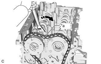
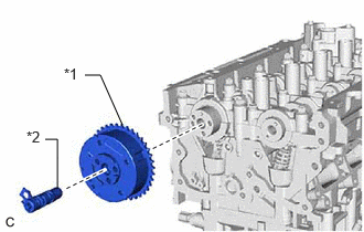
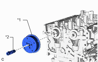
- REMOVE CAMSHAFT TIMING GEAR ASSEMBLY
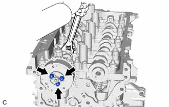
- Hold the hexagonal portion of the No. 2 camshaft with a wrench and turn the camshaft timing exhaust gear assembly clockwise to loosen the chain sub-assembly between the camshaft timing exhaust gear assembly and camshaft timing gear assembly.
*a Loosen 
Turn - Using a wrench, hold the hexagonal portion of the camshaft.NOTE:
- Be careful not to damage the camshaft housing sub-assembly, cylinder head sub-assembly and spark plug tube with the wrench.
- Do not disassemble the camshaft timing gear assembly.
*a Hold Turn - Using a 10 mm bi-hexagon socket wrench, remove the bolt and camshaft timing gear assembly from the camshaft.
- Hold the hexagonal portion of the No. 2 camshaft with a wrench and turn the camshaft timing exhaust gear assembly clockwise to loosen the chain sub-assembly between the camshaft timing exhaust gear assembly and camshaft timing gear assembly.
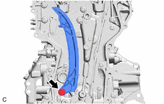
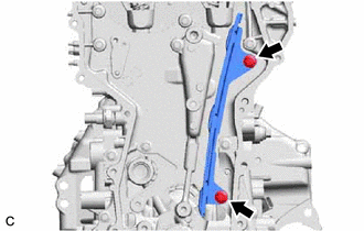
- REMOVE CHAIN SUB-ASSEMBLY
- REMOVE NO. 1 CHAIN TENSIONER ASSEMBLY
- REMOVE CHAIN TENSIONER SLIPPER
- REMOVE NO. 1 CHAIN VIBRATION DAMPER
- REMOVE CAMSHAFT TIMING EXHAUST GEAR ASSEMBLY
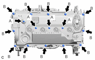
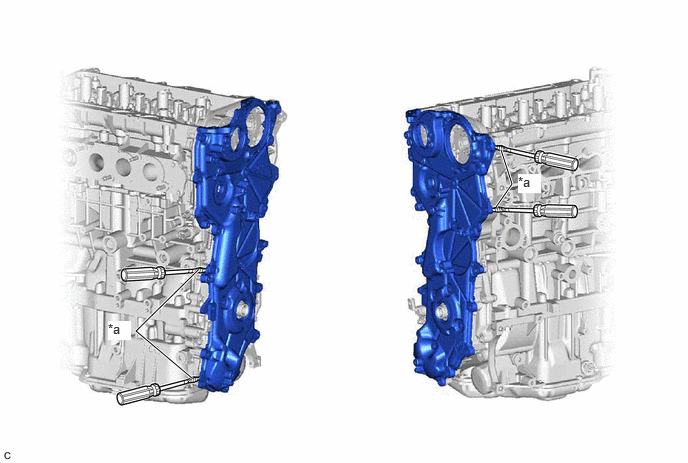
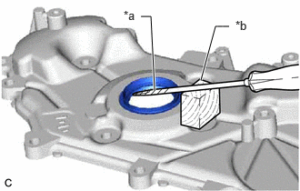
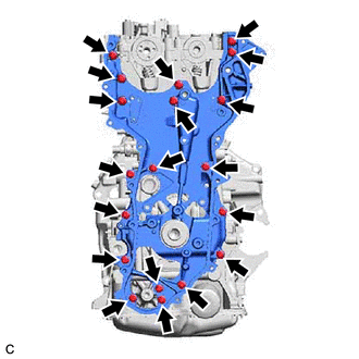
- REMOVE TIMING CHAIN COVER ASSEMBLY
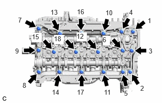
- Remove the 19 bolts from the camshaft housing sub-assembly, cylinder head sub-assembly, cylinder block sub-assembly, stiffening crankcase assembly and oil pump assembly.
- Remove the timing chain cover assembly by prying between the cylinder head sub-assembly, camshaft housing sub-assembly, cylinder block sub-assembly, oil pump assembly and stiffening crankcase assembly with a screwdriver with its tip wrapped with protective tape.
*a Protective Tape - - NOTE:Be careful not to damage the contact surfaces of the cylinder head sub-assembly, camshaft housing sub-assembly, cylinder block sub-assembly, oil pump assembly, stiffening crankcase assembly and timing chain cover assembly.
- Remove the 19 bolts from the camshaft housing sub-assembly, cylinder head sub-assembly, cylinder block sub-assembly, stiffening crankcase assembly and oil pump assembly.
- REMOVE OIL NOZZLE VALVE SUB-ASSEMBLY
- REMOVE CRANKSHAFT TIMING GEAR KEY
- REMOVE FUEL PUMP LIFTER GUIDE
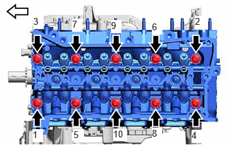
- REMOVE CAMSHAFT HOUSING SUB-ASSEMBLY
- Uniformly loosen and remove the 18 bolts in the order shown in the illustration.
- Remove the camshaft housing sub-assembly by prying between the cylinder head sub-assembly and camshaft housing sub-assembly with a screwdriver.NOTE:
Be careful not to damage the contact surfaces of the cylinder head sub-assembly and camshaft housing sub-assembly.
HINT:
Tape the screwdriver tip before use.
- Uniformly loosen and remove the 18 bolts in the order shown in the illustration.
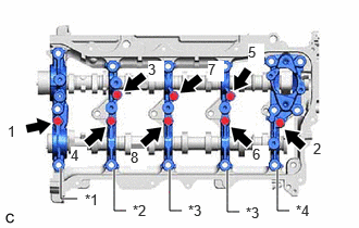
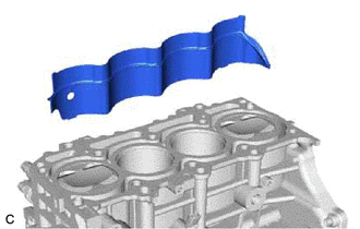
- REMOVE CAMSHAFT BEARING CAP
- Remove the 8 bolts in the order shown in the illustration.
*1 No. 1 Camshaft Bearing Cap *2 No. 2 Camshaft Bearing Cap *3 No. 3 Camshaft Bearing Cap *4 No. 4 Camshaft Bearing Cap - Remove the No. 1 camshaft bearing cap, No. 2 camshaft bearing cap, 2 No. 3 camshaft bearing caps and No. 4 camshaft bearing cap.
HINT:
Arrange the removed parts in such a way that they can be reinstalled to their original locations.
- Remove the 8 bolts in the order shown in the illustration.
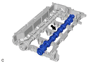
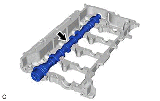
- REMOVE CAMSHAFT
- REMOVE NO. 2 CAMSHAFT
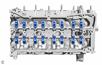
- REMOVE NO. 1 VALVE ROCKER ARM SUB-ASSEMBLY
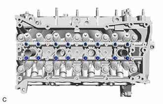
- REMOVE VALVE LASH ADJUSTER ASSEMBLY
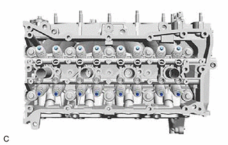
- REMOVE VALVE STEM CAP
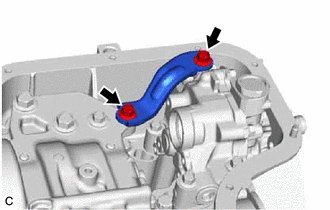
- REMOVE WATER BY-PASS PIPE SUB-ASSEMBLY
- REMOVE CYLINDER HEAD SUB-ASSEMBLY
- Using a 12 mm socket wrench, uniformly loosen the 10 cylinder head set bolts in the order shown in the illustration. Remove the 10 cylinder head set bolts and 10 plate washers.

Front of Engine NOTE:- Be careful not to drop the plate washers into the cylinder head sub-assembly.
- Warpage or cracking of the cylinder head sub-assembly may result from removing the cylinder head set bolts in the incorrect order.
HINT:
Arrange the removed parts in such a way that they can be reinstalled to their original locations.
- Remove the cylinder head sub-assembly from the cylinder block sub-assembly.
- Using a 12 mm socket wrench, uniformly loosen the 10 cylinder head set bolts in the order shown in the illustration. Remove the 10 cylinder head set bolts and 10 plate washers.
- REMOVE CYLINDER HEAD GASKET
Refer to PROCEDURE - Step 65
- REMOVE CYLINDER BLOCK WATER JACKET SPACER
- REMOVE OIL FILTER SUB-ASSEMBLY
Refer to PROCEDURE - Step 3
- REMOVE OIL PAN DRAIN PLUG
- Remove the oil pan drain plug and gasket from the No. 2 oil pan sub-assembly.
- REMOVE OIL FILTER UNION
- Using a 12 mm straight hexagon wrench, remove the oil filter union from the stiffening crankcase assembly.
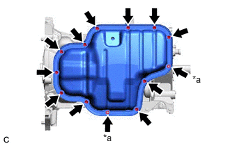
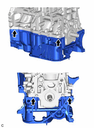
- REMOVE NO. 2 OIL PAN SUB-ASSEMBLY
- Remove the 11 bolts and 2 nuts.
*a Nut - Insert the blade of an oil pan seal cutter between the No. 2 oil pan sub-assembly and stiffening crankcase assembly, cut through the applied sealer and remove the No. 2 oil pan sub-assembly.NOTE:
- Be careful not to damage the contact surfaces of the stiffening crankcase assembly and No. 2 oil pan sub-assembly.
- Be careful not to damage the No. 2 oil pan sub-assembly flange.
- Remove the 11 bolts and 2 nuts.
- REMOVE OIL STRAINER SUB-ASSEMBLY
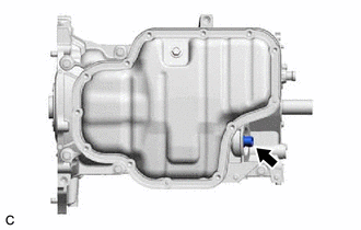
- REMOVE ENGINE OIL LEVEL SENSOR
Refer to PROCEDURE - Step 4
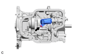
- REMOVE OIL PUMP BRACKET
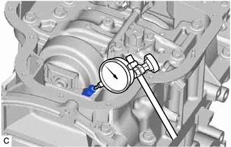
- INSPECT CRANKSHAFT BACKLASH
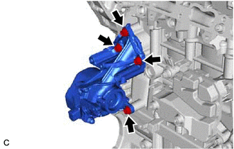
- REMOVE ENGINE BALANCER ASSEMBLY
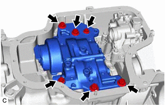
- REMOVE OIL PUMP ASSEMBLY
Refer to PROCEDURE - Step 7
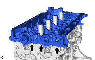
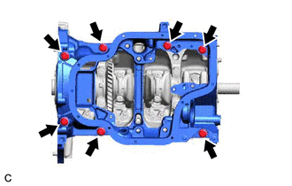
- REMOVE STIFFENING CRANKCASE ASSEMBLY
- Remove the 7 bolts.
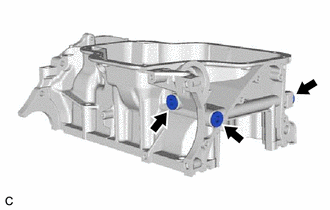
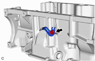
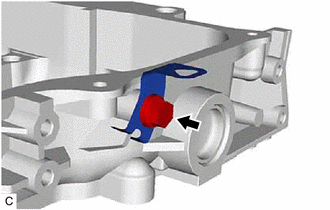
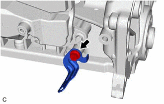
- Using a screwdriver, remove the stiffening crankcase assembly by prying between the stiffening crankcase assembly and cylinder block sub-assembly at the places shown in the illustration.NOTE:
Be careful not to damage the contact surfaces of the cylinder block sub-assembly and stiffening crankcase assembly.
HINT:
Tape the screwdriver tip before use.
- Remove the 7 bolts.
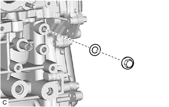
- REMOVE STRAIGHT SCREW PLUG
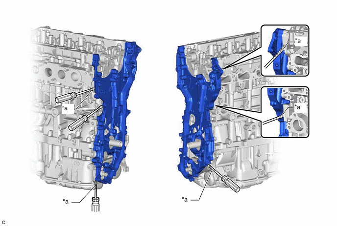
- REMOVE WIRE HARNESS CLAMP BRACKET
- Stiffening crankcase assembly side:
- Camshaft housing sub-assembly side:
- Cylinder block sub-assembly side:
- REMOVE STUD BOLT NOTE:
If a stud bolt is deformed or its threads are damaged, replace it.
- REMOVE RING PIN NOTE:
It is not necessary to remove the ring pins unless they are being replaced.
- REMOVE STRAIGHT PIN NOTE:
It is not necessary to remove the straight pins unless they are being replaced.
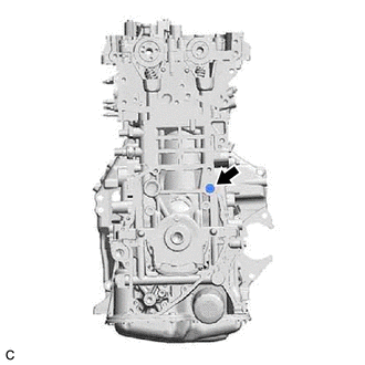
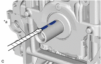
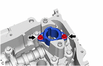
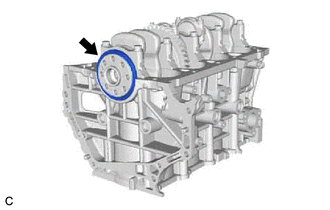
- REMOVE REAR ENGINE OIL SEAL