Installation [12/2019 - 11/2023]: Procedure
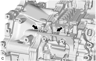
- INSTALL TUBE CONNECTOR
HINT:
Perform this procedure only when replacement of the tube connector or O-ring is necessary.
- Coat 2 new O-rings with Toyota Genuine ATF WS and install them to the 2 tube connectors.
- Using a 19 mm deep socket wrench, install the 2 tube connectors to the hybrid vehicle transaxle assembly.
Torque: 15 N.m (153 kgf/cm, 11 ft.lbf)
- INSTALL TRANSAXLE BREATHER PLUG
HINT:
Perform this procedure only when replacement of the transaxle breather plug is necessary.
- Install the transaxle breather plug to the hybrid vehicle transaxle assembly.
Torque: 11.3 N.m (115 kgf/cm, 8 ft.lbf)
- Install the transaxle breather plug to the hybrid vehicle transaxle assembly.
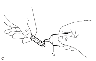
- INSTALL STUD BOLT
- Clean and degrease the 2 stud bolts and 2 stud bolt holes.
- Apply adhesive to 2 or 3 threads on the ends of the 2 stud bolts.
*a Adhesive Adhesive
Toyota Genuine Adhesive 1324, Three Bond 1324 or equivalent
NOTE:In order to ensure proper sealing of the 2 stud bolts, install them within 10 minutes of applying adhesive.
- Using a E10 "TORX" socket wrench, install the 2 stud bolts to the hybrid vehicle transaxle assembly.
Torque: 30 N.m (306 kgf/cm, 22 ft.lbf)
- Clean and degrease the 2 stud bolts and 2 stud bolt holes.
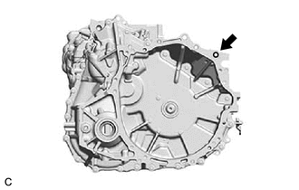
- INSTALL TRANSAXLE HOUSING PLUG
- Install the transaxle housing plug and a new gasket to the hybrid vehicle transaxle assembly.
Torque: 39.2 N.m (400 kgf/cm, 29 ft.lbf)
- Install the transaxle housing plug and a new gasket to the hybrid vehicle transaxle assembly.
- INSTALL WIRE HARNESS CLAMP BRACKET
- INSTALL TRANSMISSION WIRE
- Install the transmission wire to the hybrid vehicle transaxle assembly with the bolt.
Torque: 13 N.m (133 kgf/cm, 10 ft.lbf)
- Connect the connector.
- Install the transmission wire to the hybrid vehicle transaxle assembly with the bolt.
- INSTALL NO. 3 INVERTER BRACKET
- INSTALL NO. 1 TRANSMISSION CONTROL CABLE BRACKET
- Install the No. 1 transmission control cable bracket to the hybrid vehicle transaxle assembly with the 2 bolts.
Torque: 12 N.m (122 kgf/cm, 9 ft.lbf)
- Install the No. 1 transmission control cable bracket to the hybrid vehicle transaxle assembly with the 2 bolts.
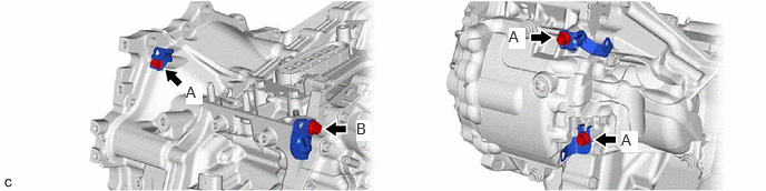
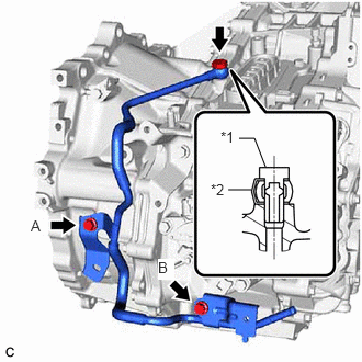
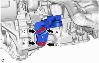
- INSTALL NO. 2 MOTOR COOLING PIPE
- Temporarily install the No. 2 motor cooling pipe to the hybrid vehicle transaxle assembly with the oil cooler union bolt and a new gasket.
*1 Oil Cooler Union Bolt *2 Gasket - Temporarily install the bolt (A).
- Install the bolt (B).
Torque: 19.5 N.m (199 kgf/cm, 14 ft.lbf)
- Tighten the bolt (A).
Torque: 19.5 N.m (199 kgf/cm, 14 ft.lbf)
- Tighten the oil cooler union bolt.
Torque: 35 N.m (357 kgf/cm, 26 ft.lbf)
- Temporarily install the No. 2 motor cooling pipe to the hybrid vehicle transaxle assembly with the oil cooler union bolt and a new gasket.
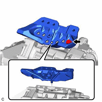
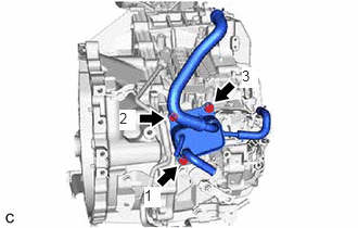
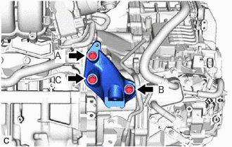
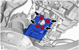
- INSTALL MOTOR COOLING COOLER
- Temporarily install the motor cooling cooler to the No. 1 transmission control cable bracket with the 3 bolts.
- Tighten the 3 bolts in the order shown in the illustration.
Torque: 11.5 N.m (117 kgf/cm, 8 ft.lbf)
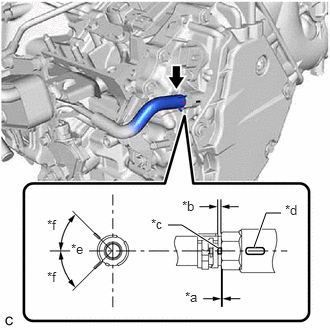
- Connect the No. 1 motor cooling hose to the tube connector, and slide the clip to secure it.
*a 0 to 3 mm (0 to 0.118 in.) *b 2 to 7 mm (0.0787 to 0.276 in.) *c Paint Mark *d Marking *e Center of Paint Mark *f 45° (Claw of Clip Location) NOTE:- Make sure to slide the No. 1 motor cooling hose until it contacts the hose stopper of the tube connector.
- Make sure to align the paint mark of the No. 1 motor cooling hose with the marking of the hybrid vehicle transaxle assembly.
- Make sure that the claws of the clip are within the location shown in the illustration.
- INSTALL MOTOR CABLE
See step 1
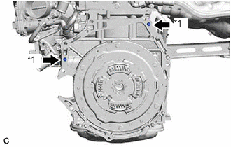
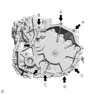
- INSTALL HYBRID VEHICLE TRANSAXLE ASSEMBLY
- Make sure that the knock pins are installed to the engine assembly.
*1 Knock Pin - Align the knock pins with the holes in the hybrid vehicle transaxle assembly and, while keeping the contact surfaces of the engine assembly and hybrid vehicle transaxle assembly in close contact with one another, temporarily install the bolt.NOTE:
- When tightening the bolts, be sure that the contact surfaces of the engine assembly and hybrid vehicle transaxle assembly are in close contact with one another.
- Do not apply grease to the inner splines of the transmission input damper assembly or input shaft assembly.
- Make sure that the wire harness or similar items are not pinched between the contact surfaces.
- Do not use excessive force when installing the hybrid vehicle transaxle assembly.
- Make sure to align the hybrid vehicle transaxle assembly so that the input shaft assembly of the hybrid vehicle transaxle assembly will be inserted straight into the inner splines of the transmission input damper assembly.
- When inserting the input shaft assembly of the hybrid vehicle transaxle assembly into the inner splines of the transmission input damper assembly, do not shake the hybrid vehicle transaxle assembly excessively.
- When installing the hybrid vehicle transaxle assembly to the engine assembly, make sure to securely fit the knock pins into the knock pin holes.
- While keeping the contact surfaces of the engine assembly and hybrid vehicle transaxle assembly in close contact with one another, install the 8 bolts.
Bolt Bolt Length Torque (A) 50 mm (1.97 in.) 64 N.m (653 kgf/cm, 47 ft.lbf) (B), (C) 45 mm (1.77 in.) 46 N.m (469 kgf/cm, 34 ft.lbf) (D) 35 mm (1.38 in.) 25 N.m (255 kgf/cm, 18 ft.lbf) HINT:
- Bolt (A), (B), (D): Install from the hybrid vehicle transaxle assembly side.
- Bolt (C): Install from the engine assembly side.
- Make sure that the knock pins are installed to the engine assembly.
- INSTALL REAR ENGINE MOUNTING BRACKET
- INSTALL REAR ENGINE MOUNTING INSULATOR
Refer to PROCEDURE - Step 11 [12/2019 - 10/2022] , or refer to PROCEDURE - Step 11 [10/2022 - 11/2023]
- INSTALL FRONT ENGINE MOUNTING BRACKET
- INSTALL FRONT ENGINE MOUNTING INSULATOR
Refer to PROCEDURE - Step 12 [12/2019 - 10/2022] , or refer to PROCEDURE - Step 12 [10/2022 - 11/2023]
- INSTALL FRONT FRAME ASSEMBLY
Refer to PROCEDURE - Step 8 [12/2019 - 10/2022] , or refer to PROCEDURE - Step 7 [10/2022 - 11/2023]
- INSTALL FLYWHEEL HOUSING SIDE COVER
- Install the flywheel housing side cover to the engine assembly.
- INSTALL OIL PUMP WITH MOTOR ASSEMBLY
See step 1
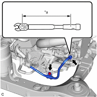
- INSTALL NO. 1 MOTOR COOLING PIPE
- Temporarily install a new flare nut of the No. 1 motor cooling pipe to the union.
*a Torque Wrench Fulcrum Length - Install the No. 2 oil cooler tube clamp and No. 1 motor cooling pipe to the No. 2 motor cooling pipe with the bolt.
Torque: 8.2 N.m (84 kgf/cm, 73 in.lbf)
- Using a 17 mm union nut wrench, tighten the flare nut to connect the No. 1 motor cooling pipe.
Specified Tightening Torque
Torque: 34.3 N.m (350 kgf/cm, 25 ft.lbf)
HINT:
- Calculate the torque wrench reading when changing the fulcrum length of the torque wrench.
Refer to PRECAUTION [12/2019 - 11/2023]
- When using a 17 mm union nut wrench (fulcrum length of 30 mm (1.18 in.)) + torque wrench (fulcrum length of 180 mm (7.09 in.)):
29.4 N.m (300 kgf/cm, 22 ft.lbf)
- Calculate the torque wrench reading when changing the fulcrum length of the torque wrench.
- Temporarily install a new flare nut of the No. 1 motor cooling pipe to the union.
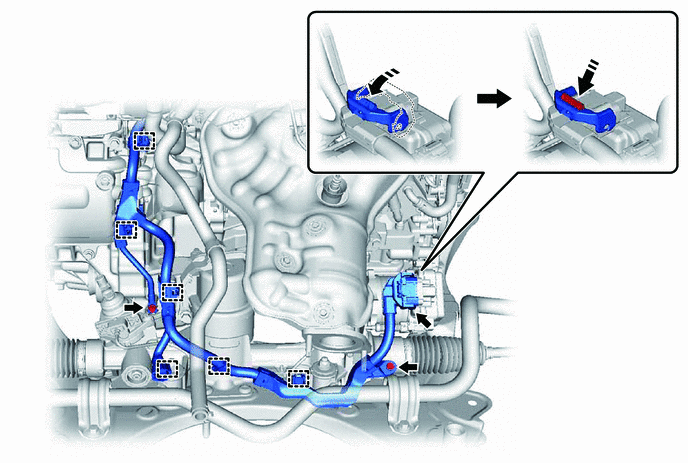
- INSTALL NO. 2 TRANSMISSION OIL COOLER HOSE ASSEMBLY
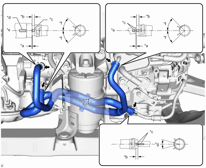
- Engage the hose clamp to install the No. 2 transmission oil cooler hose assembly to the No. 2 motor cooling pipe.
*a 0 to 3 mm (0 to 0.118 in.) *b 2 to 7 mm (0.0787 to 0.276 in.) *c Paint Mark *d Marking *e Center of Paint Mark *f 45° (Claw of Clip Location) *g 30° (Center of Clip Location) - - - Connect the No. 2 transmission oil cooler hose assembly to the No. 1 motor cooling pipe and slide the clip to secure it.NOTE:
- Make sure to slide the No. 2 transmission oil cooler hose assembly until it contacts the hose stopper of the No. 1 motor cooling pipe.
- Make sure to align the paint mark of the No. 2 transmission oil cooler hose assembly with the paint mark of the No. 1 motor cooling pipe.
- Make sure that the claws of the clip are within the location shown in the illustration.
- Connect the No. 2 transmission oil cooler hose assembly to the motor cooling cooler and slide the clip to secure it.NOTE:
- Make sure to slide the No. 2 transmission oil cooler hose assembly until it contacts the hose stopper of the motor cooling cooler.
- Make sure to align the paint mark of the No. 2 transmission oil cooler hose assembly with the paint mark of the motor cooling cooler.
- Make sure that the claws of the clip are within the location shown in the illustration.
- Connect the No. 2 transmission oil cooler hose assembly to the oil pump with motor assembly and slide the 2 clips to secure it.NOTE:
- Make sure to slide the No. 2 transmission oil cooler hose assembly until it contacts the hose stopper of the oil pump with motor assembly.
- Make sure to align the paint mark on each No. 2 transmission oil cooler hose assembly with each marking on the oil pump with motor assembly.
- Make sure that the claws of the clip are within the location shown in the illustration.
- Engage the hose clamp to install the No. 2 transmission oil cooler hose assembly to the No. 2 motor cooling pipe.
- INSTALL TRANSAXLE UNDER STOPPER BRACKET
- CONNECT WATER HOSE
- Engage the clamp to connect the water hose.
- CONNECT HV AIR CONDITIONING WIRE
- Engage the guide to connect the HV air conditioning wire to the hybrid vehicle transaxle assembly.
- Connect the HV air conditioning wire to the hybrid vehicle transaxle assembly with the 2 bolts.
Torque: 20 N.m (204 kgf/cm, 15 ft.lbf)
- CONNECT ENGINE WIRE
- Front side:
- Connect the engine wire with the 2 bolts.
Torque: 20 N.m (204 kgf/cm, 15 ft.lbf)
- Connect the engine wire with the 2 bolts.
- Rear side:
- Engage the 6 clamps to connect the engine wire.
- Connect the engine wire with the 2 bolts.
Torque: 10 N.m (102 kgf/cm, 7 ft.lbf)
- Connect the wire harness connector to the rack and pinion power steering gear assembly.
HINT:
Make sure that the connector is fully inserted before rotating the lock lever to engage the lock.
- Engage the 6 clamps to connect the engine wire.
- Front side:
- INSTALL STEERING GEAR HEAT INSULATOR
Refer to PROCEDURE - Step 8 [12/2019 - 10/2022] , or refer to PROCEDURE - Step 7 [10/2022 - 11/2023]
- INSTALL ENGINE ASSEMBLY WITH TRANSAXLE
Refer to INSTALLATION [12/2019 - 10/2022] , or refer to INSTALLATION [10/2022 - 11/2023]
- PERFORM RESOLVER LEARNING NOTE:
If the hybrid vehicle transaxle assembly has been replaced, make sure to perform resolver learning.
- for 2WD:
Refer to UTILITY [12/2019 - 11/2023]
- for AWD:
Refer to UTILITY [12/2019 - 11/2023]
- for 2WD: