Installation [12/2019 - 10/2022]: Procedure
- INSTALL NO. 2 EXHAUST MANIFOLD HEAT INSULATOR
- for Type A:
- Install the No. 2 exhaust manifold heat insulator to the exhaust manifold (TWC: Front Catalyst) with the 6 bolts.
Torque: 11 N.m (112 kgf/cm, 8 ft.lbf)
- Install the No. 2 exhaust manifold heat insulator to the exhaust manifold (TWC: Front Catalyst) with the 6 bolts.
- for Type B:
- Install the No. 2 exhaust manifold heat insulator to the exhaust manifold (TWC: Front Catalyst) with the 3 bolts.
Torque: 11 N.m (112 kgf/cm, 8 ft.lbf)
- Install the No. 2 exhaust manifold heat insulator to the exhaust manifold (TWC: Front Catalyst) with the 3 bolts.
- for Type A:
- INSTALL EXHAUST MANIFOLD (TWC: Front Catalyst)
- Install a new exhaust manifold to head gasket to the cylinder head sub-assembly.
- Temporarily install the exhaust manifold (TWC: Front Catalyst) and No. 1 exhaust manifold heat insulator.
HINT:
At this time, do not install the parts with bolts or nuts.
-
 Courtesy of © TOYOTA, LICENSE AGREEMENT TMS1002
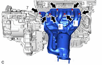
Temporarily install the exhaust manifold (TWC: Front Catalyst) to the cylinder head sub-assembly with 7 new nuts.
- Tighten the 7 nuts in the order shown in the illustration.
Torque: 26 N.m (265 kgf/cm, 19 ft.lbf)
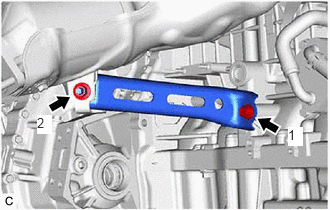
- INSTALL MANIFOLD STAY
- Temporarily install the manifold stay to the exhaust manifold (TWC: Front Catalyst) and cylinder block sub-assembly with the bolt and nut.
- Tighten the bolt and nut in the order shown in the illustration.
Torque: 43 N.m (438 kgf/cm, 32 ft.lbf)
- INSTALL NO. 1 EXHAUST MANIFOLD HEAT INSULATOR
- for Type A:
- Install the No. 1 exhaust manifold heat insulator to the exhaust manifold (TWC: Front Catalyst) with the 5 bolts.
Torque: 10 N.m (102 kgf/cm, 7 ft.lbf)
- Install the No. 1 exhaust manifold heat insulator to the exhaust manifold (TWC: Front Catalyst) with the 5 bolts.
- for Type B:
- Install the No. 1 exhaust manifold heat insulator to the exhaust manifold (TWC: Front Catalyst) with the 3 bolts.
Torque: 10 N.m (102 kgf/cm, 7 ft.lbf)
- Install the No. 1 exhaust manifold heat insulator to the exhaust manifold (TWC: Front Catalyst) with the 3 bolts.
- for Type A:
- INSTALL WIRE HARNESS CLAMP BRACKET
- Install the wire harness clamp bracket with the bolt.
Torque: 13 N.m (133 kgf/cm, 10 ft.lbf)
- Install the wire harness clamp bracket with the bolt.
- INSTALL AIR FUEL RATIO SENSOR (for Sensor 1)
Refer to INSTALLATION [12/2019 - ]
- INSTALL FRONT EXHAUST PIPE ASSEMBLY (TWC: Rear Catalyst)
- Install 2 new gaskets to the front exhaust pipe assembly (TWC: Rear Catalyst).
- Connect the front exhaust pipe assembly (TWC: Rear Catalyst) to the 2 exhaust pipe supports.
- Install the front exhaust pipe assembly (TWC: Rear Catalyst) to the exhaust manifold (TWC: Front Catalyst) and tail exhaust pipe assembly with 2 new bolts and 2 new nuts.
Torque: 43 N.m (438 kgf/cm, 32 ft.lbf)
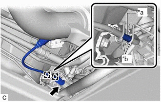
- Connect the air fuel ratio sensor (for sensor 2) connector.
*a Tube *b Wire Harness Clamp - Engage the 2 wire harness clamps so that the tube is positioned as shown in the illustration.
- Connect the outlet heater water hose D and inlet heater water hose D to the No. 2 outlet water pipe and inlet water pipe and slide the 2 clips to secure them.NOTE:
When installing the outlet heater water hose D and inlet heater water hose D, ensure that the exhaust heat recirculation system is filled with coolant. Otherwise, the engine water pump assembly may be damaged.
- INSTALL COWL VENTILATOR PANEL SUB-ASSEMBLY
Refer to PROCEDURE - Step 15
- INSTALL FRONT UPPER SUSPENSION TO COWL BRACE SUB-ASSEMBLY LH
Refer to PROCEDURE - Step 16
- INSTALL FRONT UPPER SUSPENSION TO COWL BRACE SUB-ASSEMBLY RH
HINT:
Perform the same procedure as for the LH side.
- INSTALL FRONT FENDER SPLASH SHIELD SEAL FRONT LH
Refer to PROCEDURE - Step 18
- INSTALL FRONT FENDER SPLASH SHIELD SEAL FRONT RH
HINT:
Perform the same procedure as for the LH side.
- INSTALL FENDER SPLASH SHIELD SUB-ASSEMBLY REAR LH
Refer to PROCEDURE - Step 20
- INSTALL FENDER SPLASH SHIELD SUB-ASSEMBLY REAR RH
HINT:
Perform the same procedure as for the LH side.
- INSTALL WINDSHIELD WIPER MOTOR AND LINK ASSEMBLY
Refer to INSTALLATION [12/2019 - ]
- ADD ENGINE COOLANT (for Engine)
Refer to PROCEDURE - Step 2
- INSPECT FOR COOLANT LEAK (for Engine)
Refer to PROCEDURE - Step 1
- INSPECT FOR EXHAUST GAS LEAK
See step 6
- INSTALL NO. 2 ENGINE UNDER COVER ASSEMBLY
Refer to PROCEDURE - Step 6